
Display panel and display apparatus using the same

a display panel and display panel technology, applied in the field of display panel and display apparatus, can solve the problem of easy crosstalk between images, and achieve the effects of reducing the crosstalk between images of display apparatus, enhancing the image quality of display apparatus, and improving chromatic dispersion problem

Active Publication Date: 2014-01-28
TCL CHINA STAR OPTOELECTRONICS TECH CO LTD
View PDF11 Cites 1 Cited by
  • Summary
  • Abstract
  • Description
  • Claims
  • Application Information

AI Technical Summary

Benefits of technology

This patent text describes a new display panel and apparatus that uses a half wave plate to create a 3D image. The panel can compensate for the color distortion of different pixel rows, improving the quality of the display and reducing image crosstalk. Overall, this technology solves the color distortion problem of conventional 3D displays and enhances the overall imaging experience.

Problems solved by technology

However, a chromatic dispersion of the left path (pixels) and the right path (pixels) can not be compensated simultaneously by the phase retarder of the pattern retarder display, and thus the image crosstalk there-between easily arises.

Method used


Image

  • Display panel and display apparatus using the same
  • Display panel and display apparatus using the same
  • Display panel and display apparatus using the same

Examples


Embodiment Construction

[0027]The following embodiments are referring to the accompanying drawings for exemplifying specific implementable embodiments of the present invention. Furthermore, directional terms described by the present invention, such as upper, lower, front, back, left, right, inner, outer, side and etc., are only directions by referring to the accompanying drawings, and thus the used directional terms are used to describe and understand the present invention, but the present invention is not limited thereto.

[0028]In the drawings, structure-like elements are labeled with like reference numerals.

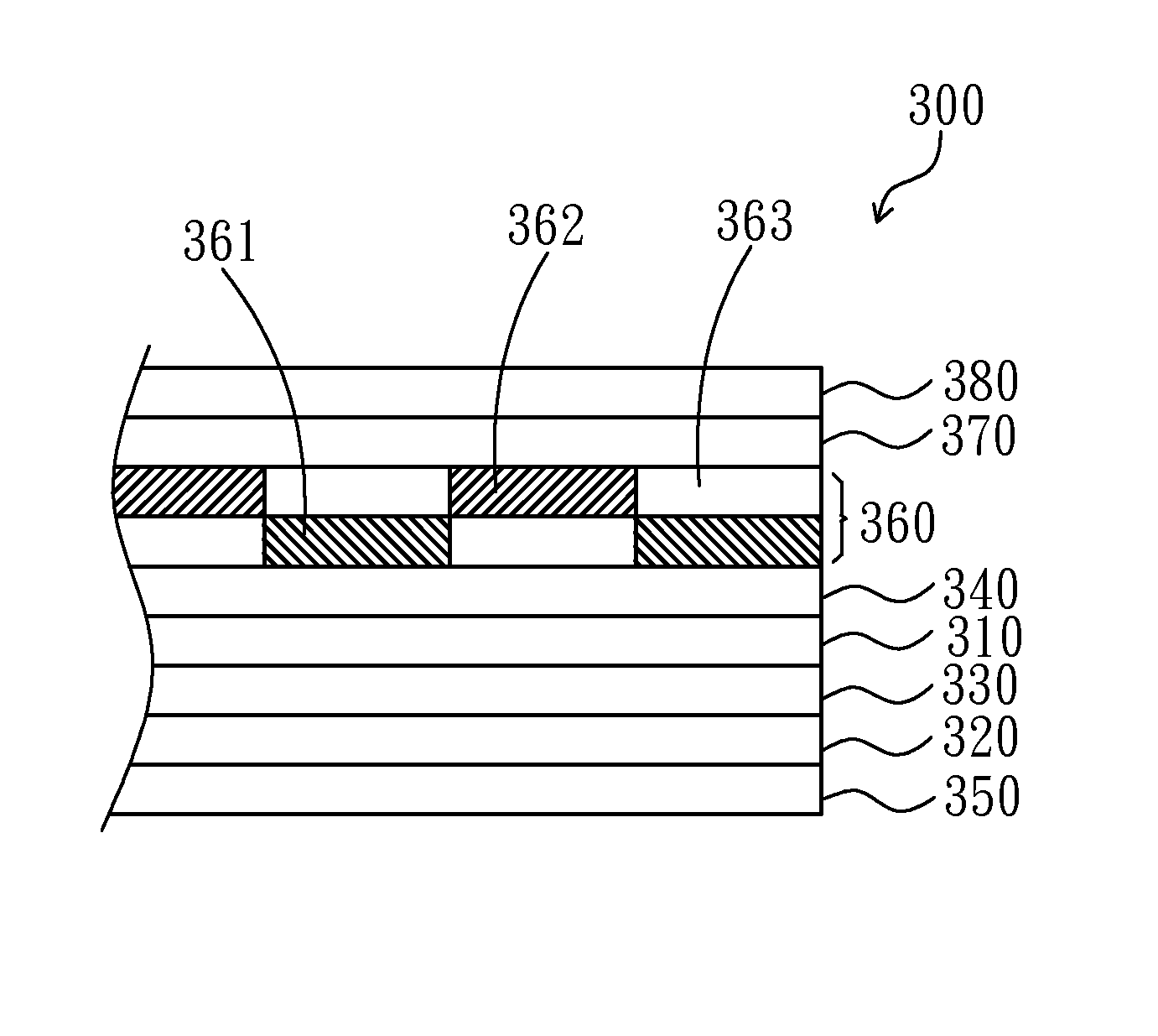
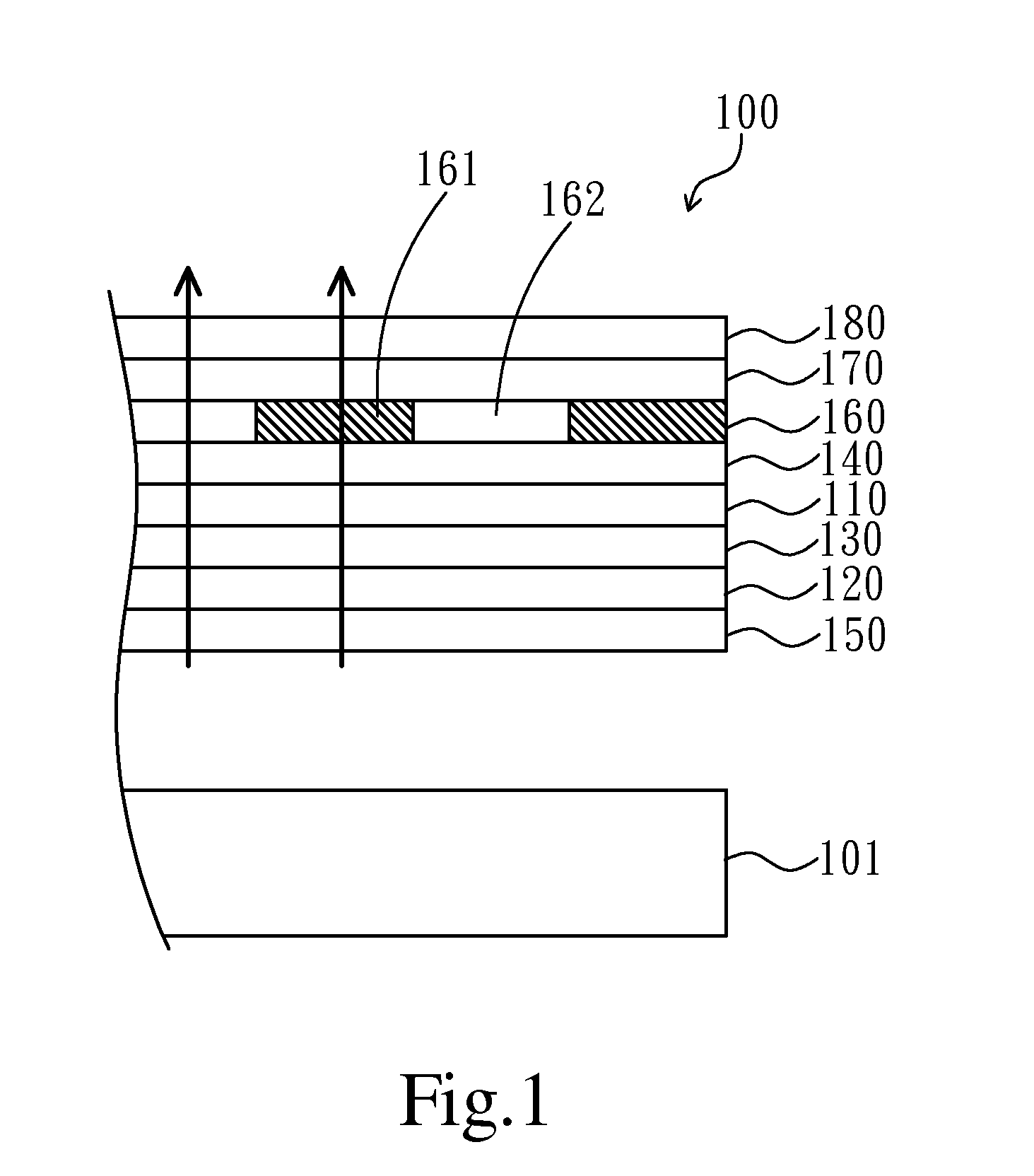
[0029]Referring to FIG. 1, a partially cross-sectional view showing a display apparatus according to a first embodiment of the present invention is illustrated. The display apparatus of the present embodiment can comprises a display panel 100 and a backlight module 101. The display panel 100 is disposed opposite to the backlight module 101, and the backlight module 101 may be realized as an edge lighti...


PUM

PropertyMeasurementUnit
angleaaaaaaaaaa
angleaaaaaaaaaa
angleaaaaaaaaaa

Abstract

The present invention provides a display panel and a display apparatus using the same. The display panel comprises a first substrate, a second substrate, a liquid crystal layer, a first polarizer, a second polarizer, a half (½) wave plate and a quarter (¼) wave plate. The liquid crystal layer is formed between the first substrate and the second substrate. The first polarizer is disposed at an outer side of the first substrate. The second polarizer is disposed at an outer side of the second substrate. The half wave plate is disposed on the first polarizer. The quarter wave plate is disposed on the half wave plate. The invention can improve a chromatic dispersion problem of a 3D display.

Description

CROSS REFERENCE TO RELATED APPLICATIONS[0001]The present application is a 35 U.S.C. §371 National Phase conversion of International (PCT) Patent Application No. PCT / CN2011 / 077983, filed on Aug. 4, 2011, the disclosure of which is incorporated by reference herein. The PCT International Patent Application was filed in Chinese.FIELD OF THE INVENTION[0002]The present invention relates to a display panel and a display apparatus using the same, and more particularly to a display panel and a display apparatus using the same for displaying a three-dimensional (3D) image.BACKGROUND OF THE INVENTION[0003]Liquid crystal displays (LCDs) have been widely applied in electrical products. Currently, most of LCDs are backlight type LCDs which include a liquid crystal panel and a backlight module.[0004]At present, the LCDs are capable of having a 3D image displaying function, such as a 3D pattern retarder display which has a quarter (¼) wave plate being disposed at an outer side of an LCD.[0005]In ge...

Claims


Application Information

Patent Timeline
Patent Type & Authority Patents(United States)
IPC IPC(8): G02F1/1335
CPCG02F2001/133638H04N13/0434G02F1/13363G02F2001/133631G02B27/26H04N13/337G02B30/25G02F1/133631G02F1/133638
Inventor HSIAO, CHIA-CHIANGCHEN, CHIH-WENHE, CHENGMING
Owner TCL CHINA STAR OPTOELECTRONICS TECH CO LTD
Features
  • Generate Ideas
  • Intellectual Property
  • Life Sciences
  • Materials
  • Tech Scout
  • Unparalleled Data Quality
  • Higher Quality Content
  • 60% Fewer Hallucinations
Learn More