
Optimum configuration for fast reactors

a technology for reactor cores and reactor cores, which is applied in the direction of nuclear reactors, nuclear elements, greenhouse gas reduction, etc., can solve the problem of no prior art suggestion to try anything other than concentric designs, and achieve the effect of increasing the ratio of inner wall surface area, reducing capital cost, and increasing thermal power

Inactive Publication Date: 2014-01-28
WESTINGHOUSE ELECTRIC CORP
View PDF16 Cites 1 Cited by
  • Summary
  • Abstract
  • Description
  • Claims
  • Application Information

AI Technical Summary

Benefits of technology

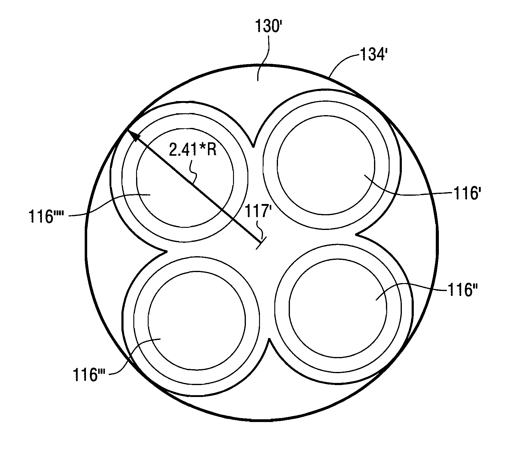
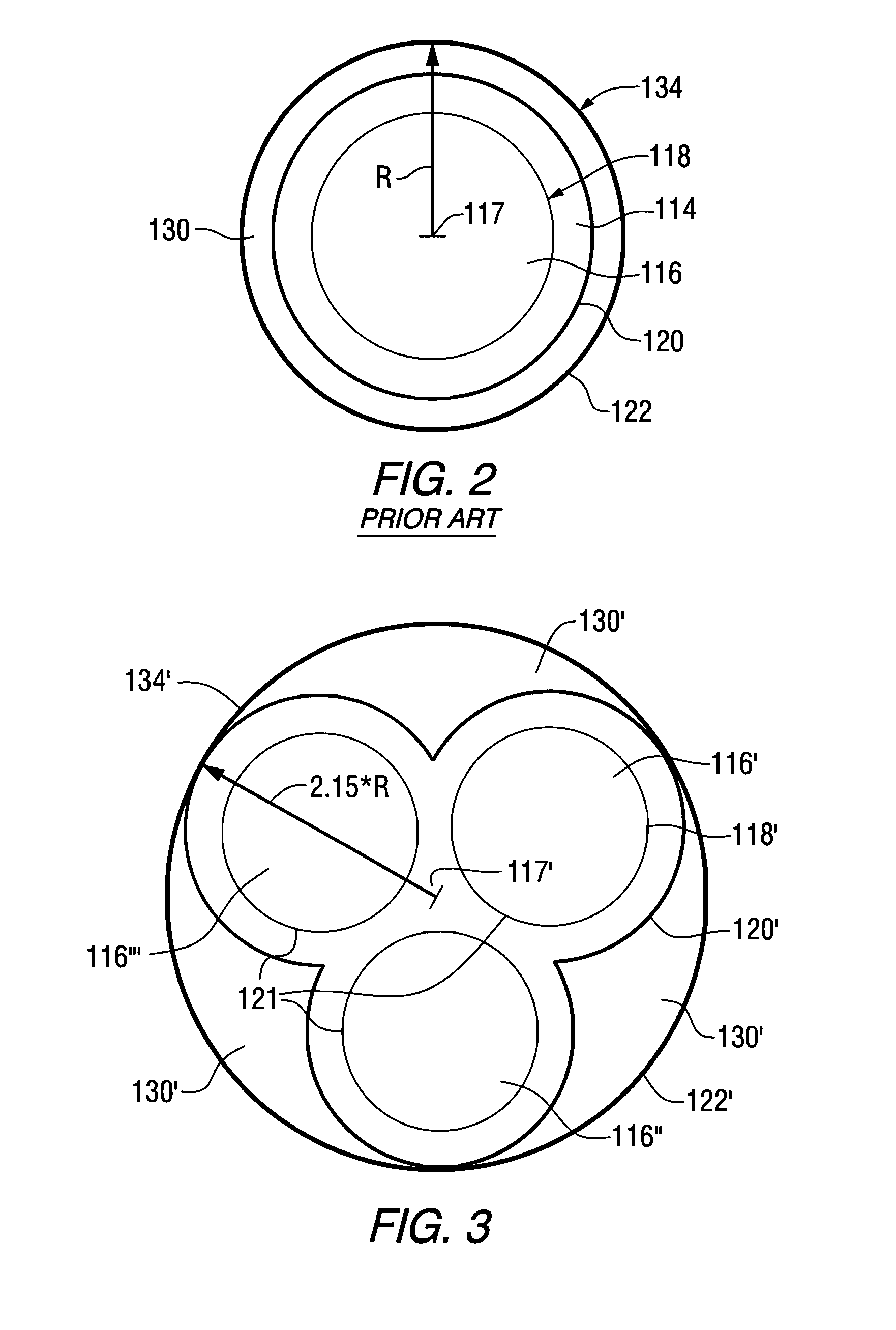
[0022]The invention also resides in a liquid metal or molten salt cooled nuclear reactor comprising a multi-lobed reactor vessel, in a closed bottom containment vessel having a cylindrical wall for holding a pool of liquid metal or molten metal salt coolant; the multi-lobed reactor vessel having at least two lobes each lobe interconnected with the other lobe and each lobe containing a fast reactor core. These cores can be run as a single unit, that is all together, or independently. This approach effectively increases the ratio of the surface area of the inner wall of the reactor vessel exterior to volume of the reactor cores, allowing significantly higher thermal powers within a given containment volume, thereby decreasing the capital cost. The closed bottom container may be further contained in a concentric containment vessel surrounded by riser portions / partitions cooled by air. Generally, the containment vessel will have a cylindrical wall. While liquid sodium is preferred, alternatives to sodium include but are not limited to sodium and potassium liquid molten metals such as lead or lead / bismuth alloys, molten salts such as NaF, KF and other molten salts.
[0023]There seems to be no prior art suggestion to try anything other than concentric designs. Prior art would appear to teach away from the dramatically different lobe design of this invention. The lobes are not a design function but contribute in a dramatic fashion to the efficiency of the reactor.

Problems solved by technology

There seems to be no prior art suggestion to try anything other than concentric designs.

Method used


Image

  • Optimum configuration for fast reactors
  • Optimum configuration for fast reactors
  • Optimum configuration for fast reactors

Examples


example

Analysis of an X Lobed (X Reactor) Geometry

[0032]

Volume of containment(single lobe)=3.14*H*(R)2

Volume of containment(X lobes)=3.14*H*(1 / cosine(90−180 / X)+1)2 [0033]Utilizing a scale factor of 0.7 which is generally used for scaling the cost of vessels and structures:

Cost ratio X / 1 lobe=[(1 / cosine(90−180 / X)+1)2]0.7=(1 / cosine(90−180 / X)+1)1.4

Power ratio X lobes / 1 lobe=X / 1=X)

Power / cost ratio X lobes / 1 lobe=(X / (1 / cosine(90−180 / X)+1)1.4.

The results of this analysis are shown in the table below. Note that for at least three lobes and up to nine lobes the power / cost ratio is higher than that for a single reactor. Thus, depending on complexity of construction, three to six lobes are most useful since increasing the number of lobes also increases the complexity of making the reactor vessel and the majority of the benefit is gained by the time a six lobed vessel is used.

[0034]

Number of ReactorsRadius of(X)ContainmentPower / Cost Ratio11.001.0022.000.7632.151.0242.411.1652.701.2463.001.2973.301....


PUM


Abstract

A nuclear reactor having a liquid metal or molten salt coolant in a riser space 130′, has a cylindrical containment vessel 134 with a reactor vessel 120′, at least two lobes 121, preferably three to nine lobes 121, each lobe 121 interconnected with the other lobe(s) and each containing a fast reactor core, 116′, 116″, 116″ and 116″″.

Description

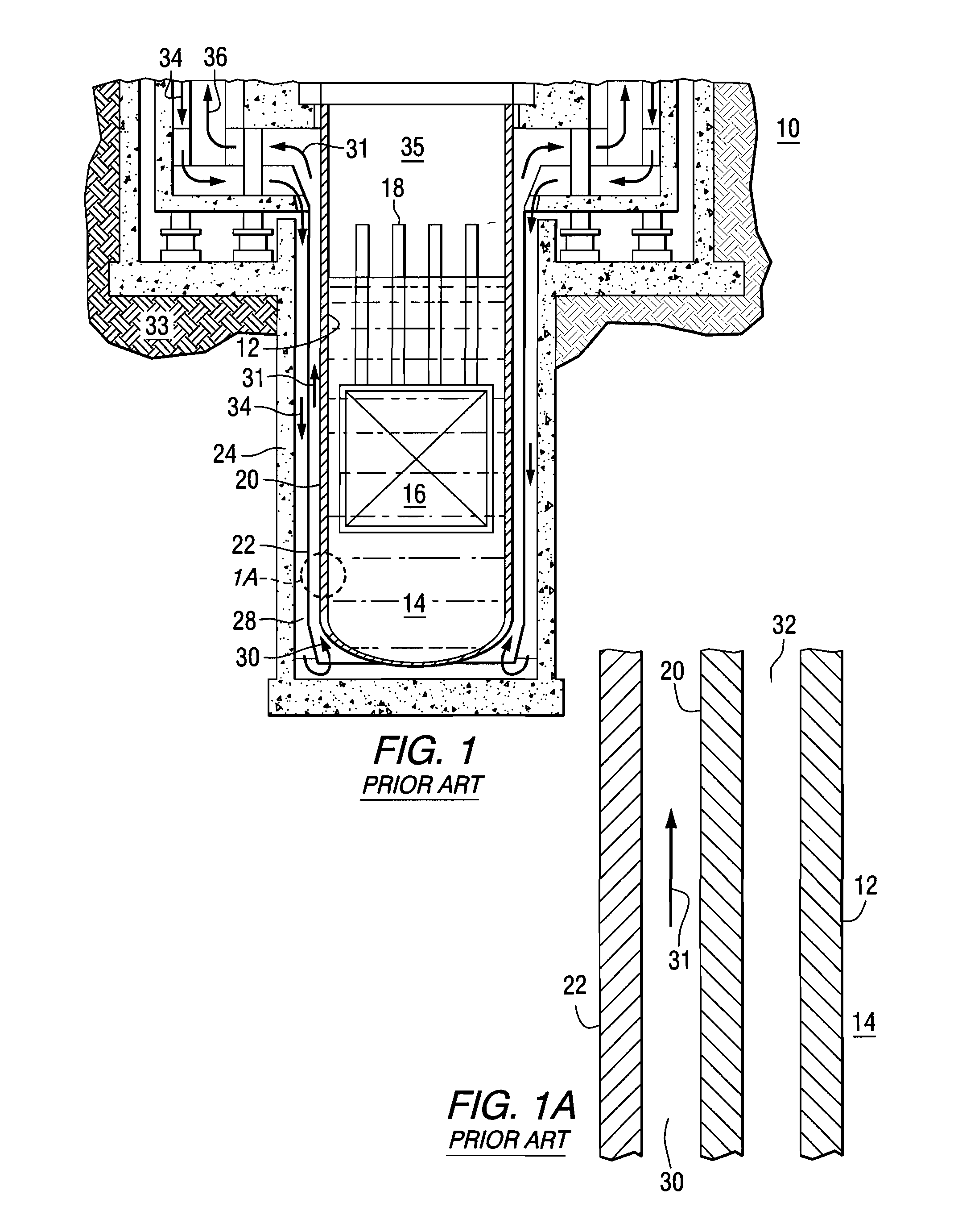
BACKGROUND OF THE INVENTION[0001]1. Field of the Invention[0002]The present invention relates to new and improved reactor core designs for fast reactors, particularly liquid metal or molten salt cooled nuclear reactors.[0003]2. Description of the Prior Art[0004]As described in Westinghouse U.S. Pat. No. 4,949,363 (Tupper et al.), a liquid metal-cooled nuclear reactor (LMR), like other nuclear reactors, operate at temperatures up to 538 C.° (1,000° F.), and produces heat by fissioning of nuclear materials which are fabricated into fuel elements and assembled within a nuclear reactor core situated in a reactor vessel. The heat produced by the LMR is used to generate electricity.[0005]Liquid sodium has excellent heat-transfer properties and low vapor pressure at temperatures of interest for power generation, and is abundant, commercially available in acceptable purity and is relative inexpensive, making it an attractive medium as a reactor coolant, for LMRs, however, it does react viol...

Claims


Application Information

Patent Timeline
Patent Type & Authority Patents(United States)
IPC IPC(8): G21C15/00G21C15/02G21C1/01G21C1/00G21C1/02
CPCG21C5/14G21C1/03Y02E30/34Y02E30/35G21C13/02Y02E30/30G21C15/18
Inventor LAHODA, EDWARD J.CARELLI, MARIO D.MEMMOTT, MATTHEW J.
Owner WESTINGHOUSE ELECTRIC CORP
Learn More