
Intake circulatory system for zinc air fuel cell

a fuel cell and circulatory system technology, applied in the direction of secondary cells, cell components, electrochemical generators, etc., can solve the problems of limited power supply efficiency limited practical use of conventional zinc air cells, and inability to generate electricity through chemical changes for a long time, so as to increase the power supply efficiency of the discharging region

Inactive Publication Date: 2016-06-30
LIAO WEN HUANG
View PDF0 Cites 0 Cited by
  • Summary
  • Abstract
  • Description
  • Claims
  • Application Information

AI Technical Summary

Benefits of technology

The invention provides a method for improving the efficiency of a zinc air fuel cell by collecting pure oxygen from the cell and supplying it to the oxidation reaction region. The fuel cell has a tubular design with a flowable zinc electrode, which can increase the surface area with oxygen for efficient discharging. The shifting device can drive the zinc electrode flow, while the air supply device can absorb and transmit external air and oxygen to the discharging region for a chemical reaction and increased power supply efficiency. The special technical feature involves the transmission of external air to the fuel cell via the air supply device and the air collecting device absorb and transmit oxygen to the air intake device for a chemical reaction and increased power supply efficiency.

Problems solved by technology

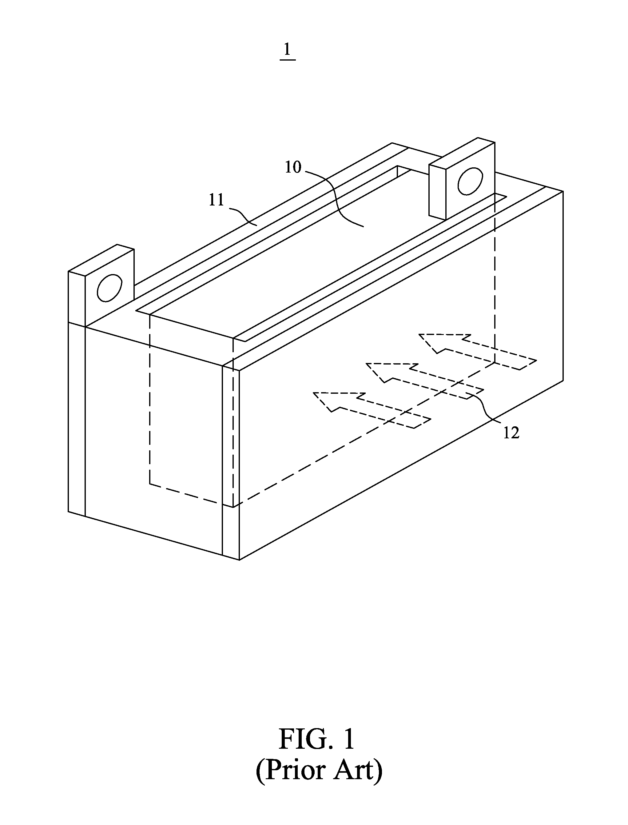
However, since the external air only contains 21% of oxygen, as such, if the generation of electricity is only by means of chemical changes, the power supply efficiency of the conventional zinc air cell 1 would be very limited.
Further, electricity generation by means of chemical changes cannot be used for a long time, to gradually increase the power supply efficiency of the conventional zinc air cell 1.
In view of the above, there are still limitations on the practical uses of the conventional zinc air cell 1, and that there is still a need to have an improvement on the conventional zinc air cell 1.

Method used


Image

  • Intake circulatory system for zinc air fuel cell
  • Intake circulatory system for zinc air fuel cell
  • Intake circulatory system for zinc air fuel cell

Examples


Embodiment Construction

[0026]The accompanying drawings are included to provide a further understanding of the invention, and are incorporated in and constitute a part of this specification. The drawings illustrate the preferred exemplary embodiments of the invention and, together with the description, serve to explain the principles of the invention.

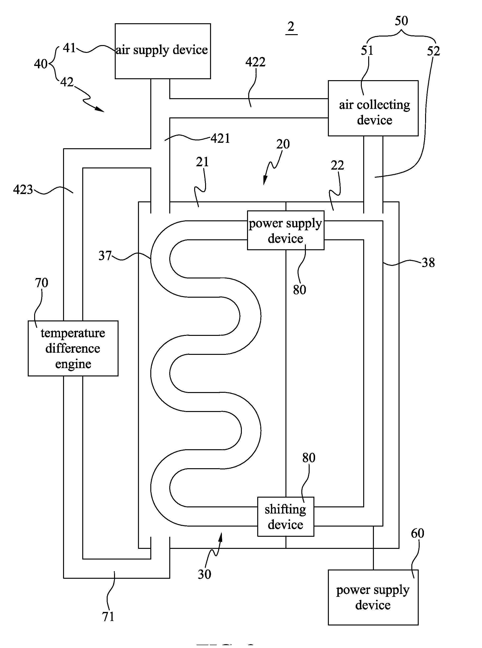
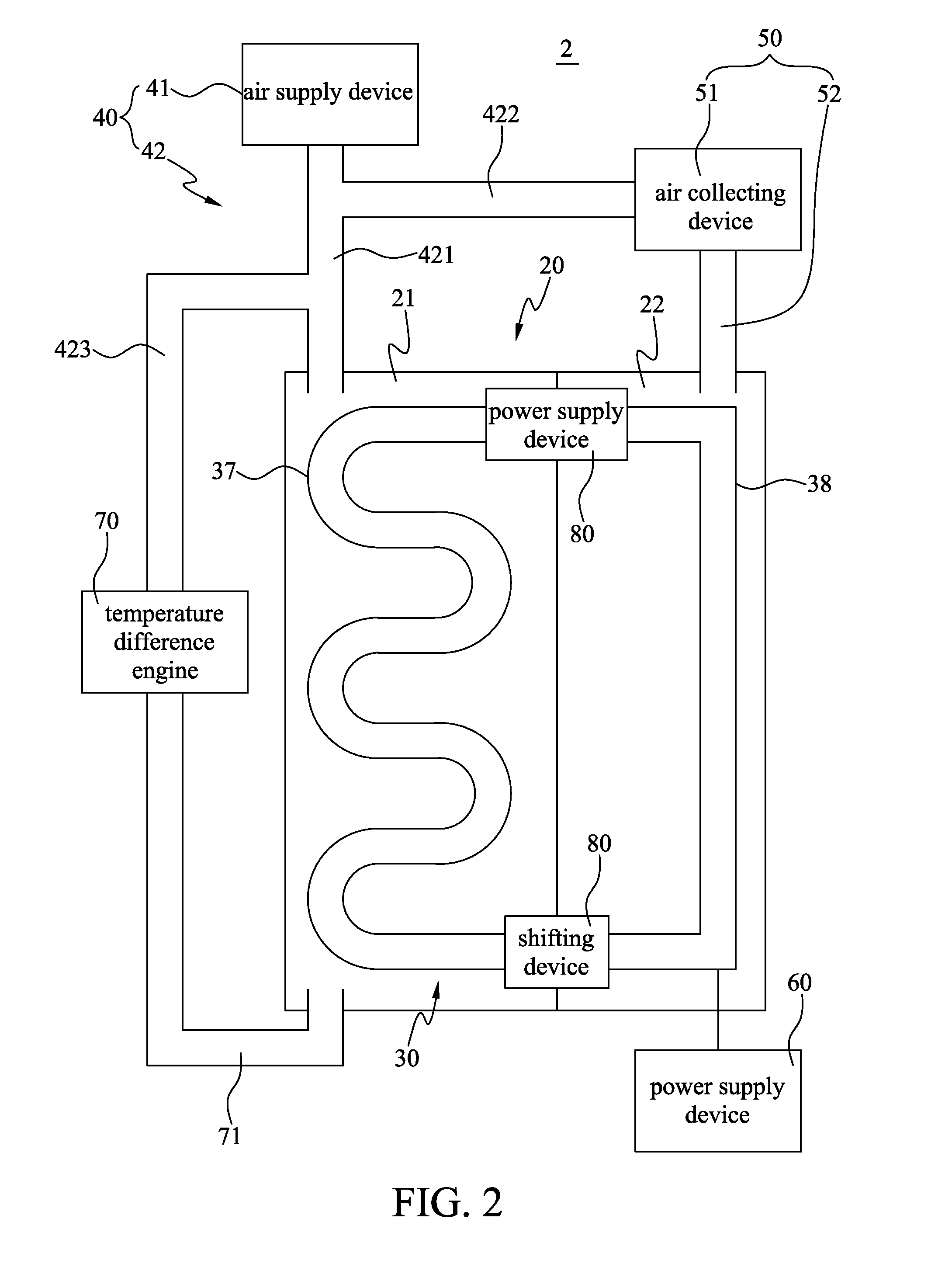
[0027]Referring to FIG. 2 to FIG. 4, in accordance with a preferred exemplary embodiment of the present invention, the intake circulatory system 2 of the zinc air fuel cell of the present invention may be mainly made up of a housing 20, a zinc air cell 30, an air supply system 40, an air collecting system 50, a power supply device 60, a temperature difference engine 70 and a shifting device 80. The housing 20 may be partitioned on the inside so as to form a first space 21 and a second space 22 that is not in connection with the first space 21.

[0028]The zinc air cell 30 may be assembled in between the first space 21 and the second space 22 of the housing 20; an...


PUM

PropertyMeasurementUnit
power supply efficiencyaaaaaaaaaa
temperatureaaaaaaaaaa
energy densityaaaaaaaaaa

Abstract

The present invention provides an intake circulatory system for a zinc air fuel cell, including a housing, a zinc air cell, an air supply system and an air collecting system. The housing is partitioned on the inside of the intake circulatory system for a zinc air fuel cell to form a first space and a second space. The zinc air cell is assembled on the inside of the housing, and includes a discharging region that is located in the first space and a charging region that is located in the second space. Moreover, the air supply system includes an air supply device and an air intake device that is in connection with the air supply device and the first space. In addition, the air collecting system includes an air collecting device that is in connection with the air intake device, and at least one air output pipe exists in between the air collecting device and the second space. Further, in accordance with the present invention, the air supply device transmits external air to the first space via the air intake device. The discharging region of the zinc air cell has a chemical reaction with oxygen from the external air to generate electricity. The charging region produces oxygen by generating electricity to perform a reduction reaction. The air collecting device absorbs oxygen and also transmits the oxygen to the air intake device. The external air and the oxygen are mixed and subsequently enter the first space. As such, the power supply efficiency of the discharging region is increased in accordance with the present invention.

Description

FIELD OF THE INVENTION[0001]The present invention relates generally to a circulatory system for a fuel cell, and more particularly, the present invention relates to a circulatory system that may enable a zinc air fuel cell to produce oxygen by performing a reduction reaction, and subsequently enabling the zinc air fuel cell to generate electricity by performing a chemical reaction.BACKGROUND OF THE INVENTION[0002]The types of cells can be classified into two main types, and these are chemical cells and physical cells. Chemical cells can be further classified into three types such as primary cell, secondary cell and fuel cell, whereby the main characteristics of a fuel cell are that a fuel cell has a positive electrode as well as a negative electrode, and active substances are not present in the fuel cell. In addition, active materials need to be supplied externally and continuously to the fuel cell, so as to enable the fuel cell to be discharged continuously. As such, in order to pr...

Claims


Application Information

Patent Timeline
Patent Type & Authority Applications(United States)
IPC IPC(8): H01M8/06H01M8/04H01M12/08H01M10/42H01M10/46
CPCH01M8/0656H01M10/4214H01M8/04201H01M12/08H01M10/46H01M8/188Y02E60/10Y02E60/50H01M50/1385
Inventor LIAO, WEN HUANG
Owner LIAO WEN HUANG
Learn More