Twisted conduit for geothermal heating and cooling systems

a geothermal heating and cooling system and conduit technology, applied in the field of conduits, can solve the problems of horizontal ground loops that require a substantial amount of land, pipe design and the cost of said design both in time and money

Active Publication Date: 2014-02-04
JENSEN ROBERT
View PDF36 Cites 4 Cited by
  • Summary
  • Abstract
  • Description
  • Claims
  • Application Information

AI Technical Summary

Problems solved by technology

However, horizontal ground loops require a substantial amount of land.
Finally, the slinky coil ground loop is a variation of the horizontal ground loop and it too requires a substantial amount of land.
Said limitation being the pipe design and the cost of said design both in terms of time and money.
This process could be costly and time consuming.
Additionally the U.S. '447 pipe inherently keeps the heat transferring fluid in the in and out flow pipes in close proximity to each other; thus causing heat contamination from the inflow to the outflow pipe.
However, this design further complicates the pipe design certification issues.
The '914 system is not designed for optimal use of the borehole due to the spacing between the secondary conduits. FIG. 1 of the '914 disclosure illustrates the fact that the '914 system requires greater land usage than a typical narrow borehole installation.
Since the borehole is a very costly part of the installation of these systems, the '914 design becomes costly to install because of the larger diameter borehole required by the '914 system.
The '914 system will be inherently more cumbersome to manage because of the flexibility of the pipe in conjunction with the spacing required between the pipes.
Specifically, it will be difficult to install the '914 invention in vertical boreholes and trenches because the pipes will tend to become disarranged from their designed arrangements.
However, this increases the cost of assembly and transportation of the '914 system.
Said insulated pipe does not contribute to the heat transfer process while occupying space in the borehole, and system efficiency is compromised.
This grout pipe can sometimes be very difficult to insert into the bore as it has a tendency to catch on various irregular surfaces.
The added spacers in the '914 configuration in conjunction with the space between pipes will make inserting this grout pipe cumbersome and laborious because the pipe may get caught on the spacers.

Method used


Image

  • Twisted conduit for geothermal heating and cooling systems
  • Twisted conduit for geothermal heating and cooling systems
  • Twisted conduit for geothermal heating and cooling systems

Examples


Embodiment Construction

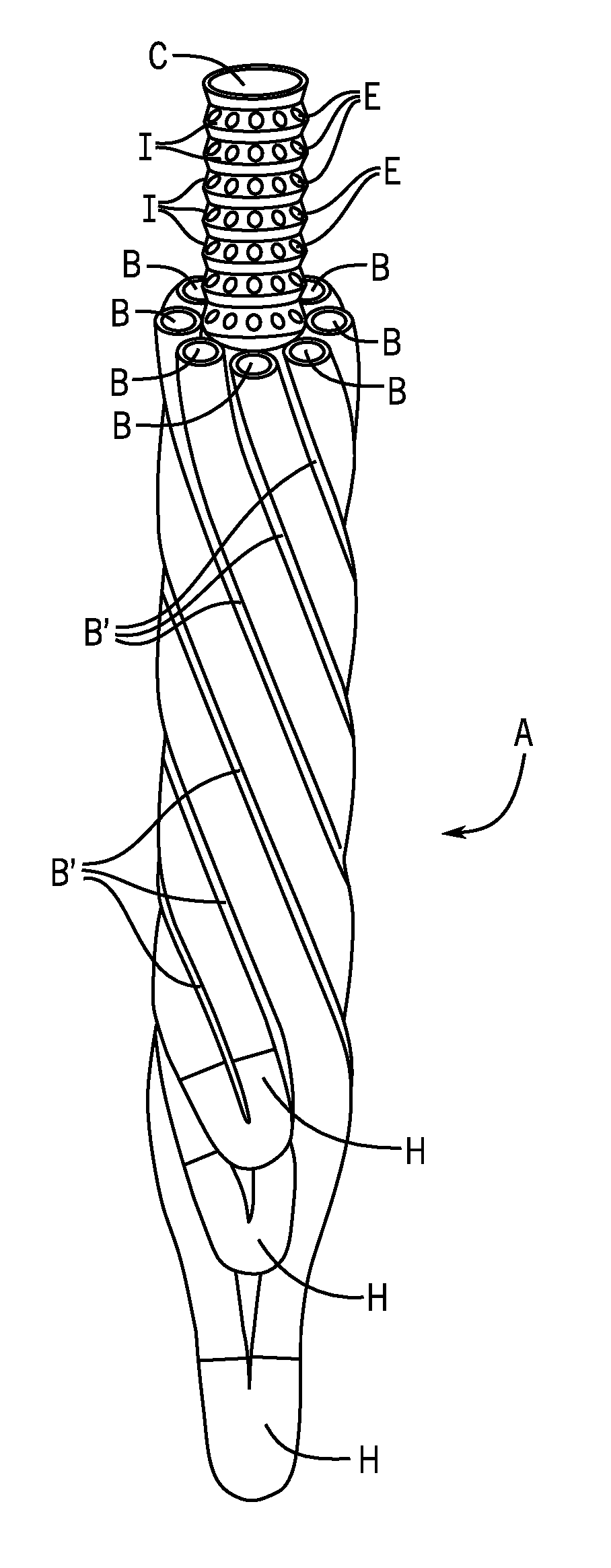
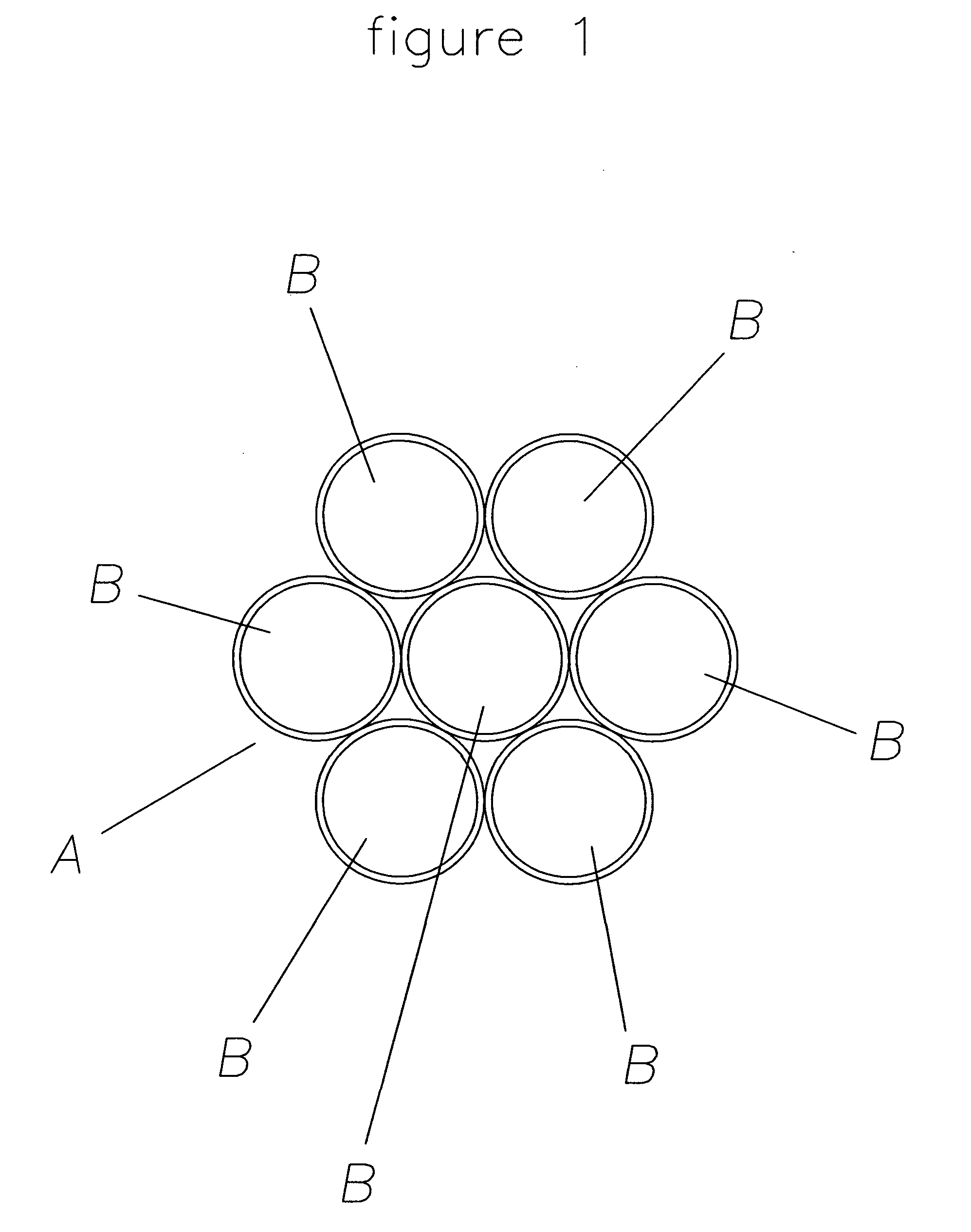
[0049]The present invention relates to a conduit for use in a geothermal heating and cooling system wherein said conduit comprises 2 or more pipes, wherein further, said 2 or more pipes comprising said conduit are twisted together.

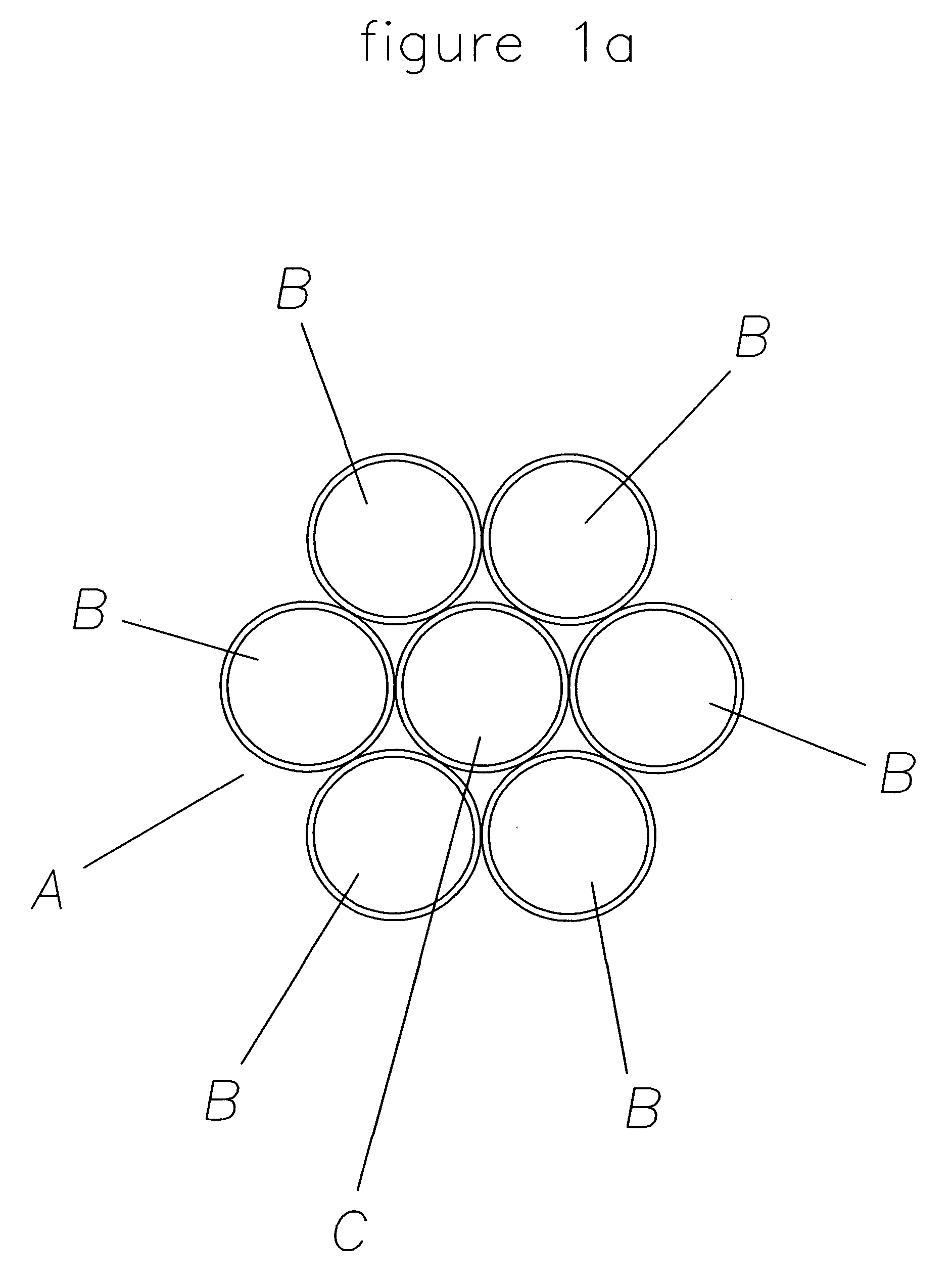
[0050]The present invention also relates to a conduit for use in a geothermal heating and cooling system wherein said conduit comprises 2 or more pipes, wherein further, said 2 or more pipes comprising said conduit are twisted together, further provided that said 2 or more twisted pipes comprising said conduit are arranged to be contiguous, arranged to be separated or arranged so that said 2 or more twisted pipes have both contiguous pipes and separated pipes.

[0051]The present invention further relates to a conduit for use in a geothermal heating and cooling system wherein said conduit comprises 2 or more pipes, wherein further, said 2 or more pipes are twisted together, further provided that said 2 or more twisted pipes are twisted around a central pipe.

[...


PUM


Abstract

The present invention relates to a conduit for use in a geothermal heating and cooling system wherein said conduit comprises 2 or more pipes, wherein said 2 or more pipes are twisted together, wherein further that said 2 or more twisted pipes are twisted around a central pipe, further provided that the functions of said central pipe include, but are not limited to, serving as a conduit for a tremie pipe, serving as a support pipe, serving as an insulating pipe or serving as a tremie pipe.

Description

[0001]This application is a Continuation-in-Part of U.S. Ser. No. 12 / 660,226, filed on Feb. 23, 2010. The entire contents of said application is hereby incorporated by reference.BACKGROUND OF THE INVENTION[0002]A. Field of the Invention[0003]The present invention relates to a conduit comprising 2 or more pipes that are twisted together. Said conduit is an integral part of a geothermal heating and cooling system. Geothermal heating and cooling systems are known for their superior performance in delivering efficient heating and cooling to homes, industrial buildings and residential and industrial complexes, as well as being environmentally clean and cost effective. See, for example,[0004]http: / / www.igshpa.okstate.edu / geothermal / geothermal.htmI;[0005]www.summitmechsystems.com / pages / 3.1.html;[0006]www.renewableheating101.com / geothermal / loops;[0007]http: / / minnesotageothermalheatpumpassociation.com / geothermal / earth-loop-options / ; and http: / / www.informedbuilding.com / Geothermal / Main16 / Types...

Claims


Application Information

Patent Timeline
Patent Type & Authority Patents(United States)
IPC IPC(8): F24J3/08
CPCY02E10/125F16L3/223F24J3/083F16L9/19F28F1/08F24T10/15Y02E10/10
Inventor JENSEN, ROBERT
Owner JENSEN ROBERT
Why Eureka
Try Eureka