Spring feeder

a feeder and spring technology, applied in the direction of conveyor parts, conveyor jigging, sorting, etc., can solve the problems of operation efficiency drop, and achieve the effects of easy catch, low pressure, and loss of air pressur

Active Publication Date: 2014-02-04
KANTO ELECTRONICS
View PDF19 Cites 7 Cited by
  • Summary
  • Abstract
  • Description
  • Claims
  • Application Information

AI Technical Summary

Benefits of technology

[0018]In accordance with the invention as set forth in claim 2, the arc-like groove region portion is positioned at the initial end side of the conveying path for connection, thereby making it possible to release the jamming of springs at a comparatively early stage. In accordance with the invention as set forth in claim 3, the air ejected from the ejection nozzle is linearly supplied into the straight groove region portion. Therefore, the loss of air pressure in the straight groove region portion is comparatively low, and the springs jamming the conveying groove for connection can be blown off and the jamming can be released, while maintaining a high pressure. In accordance with the invention as set forth in claim 4, it is possible to remove the jamming of the boundary groove region portion, which is the boundary between the arc-like groove region portion and the straight groove region portion, where the defective springs can be most easily caught.
[0019]In accordance with the invention as set forth in claim 5, the air jet of the ejection portion for spring removal is operated intermittently by a timer control. Therefore, the jamming can be released periodically and stable feed of the springs can be maintained. In accordance with the invention as set forth in claim 6, a cover member is provided along the conveying direction of the springs in the conveying groove for connection, a gap is provided between the conveying groove for connection and the cover member, and a distal end of the ejection nozzle is brought close to the gap. As a result, when the springs jamming the inside of the conveying gap for connection are removed, the springs can be returned to a specific position in a concentrated manner, without scattering a large number of springs around the feeder.
[0020]In accordance with the invention as set forth in claim 7, practically all defective springs such as tangled springs and deformed springs are sifted out in the process of conveying from the first sorting and conveying portion to the second sorting and conveying portion. In accordance with the invention as set forth in claim 8, defective springs such as tangled springs and deformed springs can be removed from the sorting notch portion in the process of conveying the springs in the first sorting and conveying portion. In accordance with the invention as set forth in claim 9, even when the tangled springs or deformed springs are only slightly different in terms of external appearance from the normal springs, these defective springs can be sifted out and the defective springs can be removed in the process of conveying the springs in the second sorting and conveying portion. All the above-described effects are demonstrated even more dramatically when the above-described springs are miniature springs.

Problems solved by technology

For this reason, the springs are often not supplied in a stable state to the operator's hands and therefore the operation efficiency drops.

Method used


Image

  • Spring feeder
  • Spring feeder
  • Spring feeder

Examples


Embodiment Construction

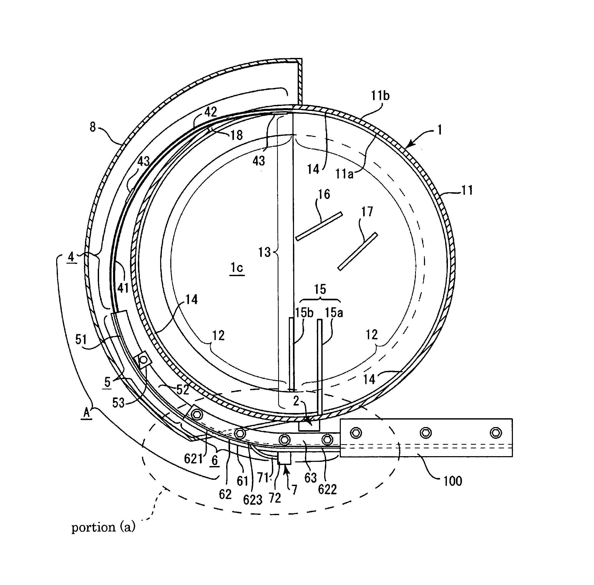
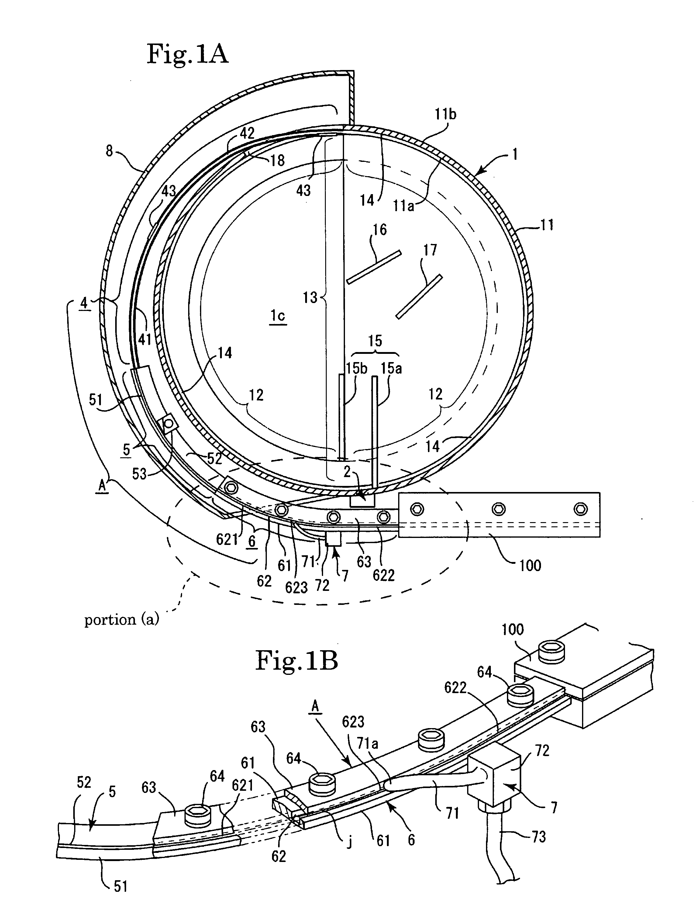
[0037]An embodiment of the present invention will be explained below with reference to the appended drawings. First, the entire configuration will be explained. As shown in FIGS. 1A, 6, and 13, the feeder in accordance with the present invention is mainly constituted by a container 1, a conveying path A for feeding, and a vibrator 9. As shown in FIGS. 13 and 14, the container 1 is formed in an almost flat cylindrical shape. The container 1 is constituted by a circumferential wall 11, a conveying path 12, and a sorting plate 13. The circumferential wall 11 is formed in an almost cylindrical shape, and the conveying path 12 is formed in the inner side surface 11a of the circumferential wall 11 (see FIGS. 1A, 13, and 14).

[0038]Further, the sorting plate 13 is formed at the upper portion 1b of the circumferential wall 11 of the container 1, and the sorting plate 13 communicates with the conveying path 12 (see FIGS. 13 to 15). An inner conveying groove 14 is formed in a corner location f...


PUM


Abstract

A spring feeder including a conveying path and a conveying portion including a conveying groove, the conveying groove having a width approximately equal to a width of the springs. The conveying path for feeding includes a first sorting and conveying portion and a second sorting and conveying portion, the first sorting and conveying portion, the second sorting and conveying portion, and the conveying portion for connection are linked consecutively from the container side. A width of the conveying groove of the second sorting and conveying portion is narrower than a width of the conveying groove of the first sorting and conveying portion and the width of the conveying groove of the second sorting and conveying portion is narrow enough to allow only one spring to be loaded in the conveying direction in the conveying groove of the second sorting and conveying portion.

Description

BACKGROUND OF THE INVENTION[0001]1. Field of the Invention[0002]The present invention relates to a spring feeder for arranging coil-type springs (in particular, springs of a very small size) in a row along the compression-elongation direction thereof and feeding the springs in a state suitable for an operation to an operator, whereby spring jamming caused by a defective spring in a conveying path for feeding of the feeder can be released.[0003]2. Description of the Related Art[0004]Spring feeders are known that serve to arrange a large number of coil-type springs in a row along the compression-elongation direction thereof and feed the springs one by one in a state suitable for an operation to an operator. In such a spring feeder, a large number of springs are loaded into a container that is subjected to vibrations by a vibrator, the large number of springs are moved inside the container, while being arranged in a row by vibrations, and the springs are fed one by one to the operator ...

Claims


Application Information

Patent Timeline
Patent Type & Authority Patents(United States)
IPC IPC(8): B65G29/00B65G47/14
CPCB65G47/1421B65G47/1457B07C5/34
Inventor SEKI, TADAYOSHI
Owner KANTO ELECTRONICS
Why Eureka
Try Eureka