Valve with a solenoid fixed to a plunger tube by a yoke

a solenoid and plunger tube technology, applied in the field of valves, can solve the problems of additional potential damage, complicated design, and loss of separate components, and achieve the effect of simple and potentially more reliable, and convenient engagemen

Active Publication Date: 2014-02-04
DANFOSS AS
View PDF19 Cites 12 Cited by
  • Summary
  • Abstract
  • Description
  • Claims
  • Application Information

AI Technical Summary

Benefits of technology

[0009]Since the yoke itself prevents removal of the solenoid from the tube, the valve is very easy to assemble and take apart without use of separate springs or similar component which may be capable of fixing the yoke to the solenoid and tube. Such separate components may complicate the design and they inevitably introduce an additional potential reason for damage. During assembly or separation of the solenoid and yoke from the tube, the separate component may become lost, or it may accidentally be substituted with a similar component for a valve of a different size etc. Accordingly, the invention provides a simpler and potentially more reliable valve.
[0013]The yoke comprises any kind of elastically deformable structure so that the tube can be engaged by the yoke. The deformable structure may further enable subsequent release of the yoke from the tube if disassembly of the valve is desired. The elastic deformability could be provided by a slit or similar perforated structure of the yoke.
[0017]The free end may have the shape of a pawl, and the pawl may, in one embodiment, extend partly towards the opening in the upper leg and partly upwards in a direction away from the lower and upper legs. In that way, the pawl may facilitate easier sliding of the tube into the passage and, simultaneously, it may better prevent movement of the tube in the opposite direction out of the passage.
[0022]In one embodiment, the arrangement of the solenoid about the tube may be enabled by a solenoid which comprises a passage through which the tube may extend. In this embodiment, the yoke may easily fix the solenoid on the tube by hindering movement of the solenoid along the tube, e.g. by arranging the yoke with the upper and lower legs on opposite sides of the solenoid and with the tube extending through openings in these two legs. In this way, the solenoid becomes fixed to the tube when the yoke is prevented from moving along the tube.
[0023]In one embodiment, the engagement between the yoke and the tube allows movement of the yoke along the tube by sliding of the tube in the aforementioned openings in the upper and lower legs of the yoke. In this case, the engagement, however, prevents removal of the yoke from the tube by introducing an upper limit-point above which the yoke are prevented from sliding.
[0026]To provide elasticity and thus allow sufficient elastic deformation to allow the locking structure to move into and out of engagement with the tube, the yoke may form a slit extending between the mentioned openings in the lower and upper legs.

Problems solved by technology

Such separate components may complicate the design and they inevitably introduce an additional potential reason for damage.
During assembly or separation of the solenoid and yoke from the tube, the separate component may become lost, or it may accidentally be substituted with a similar component for a valve of a different size etc.

Method used


Image

  • Valve with a solenoid fixed to a plunger tube by a yoke
  • Valve with a solenoid fixed to a plunger tube by a yoke
  • Valve with a solenoid fixed to a plunger tube by a yoke

Examples


Embodiment Construction

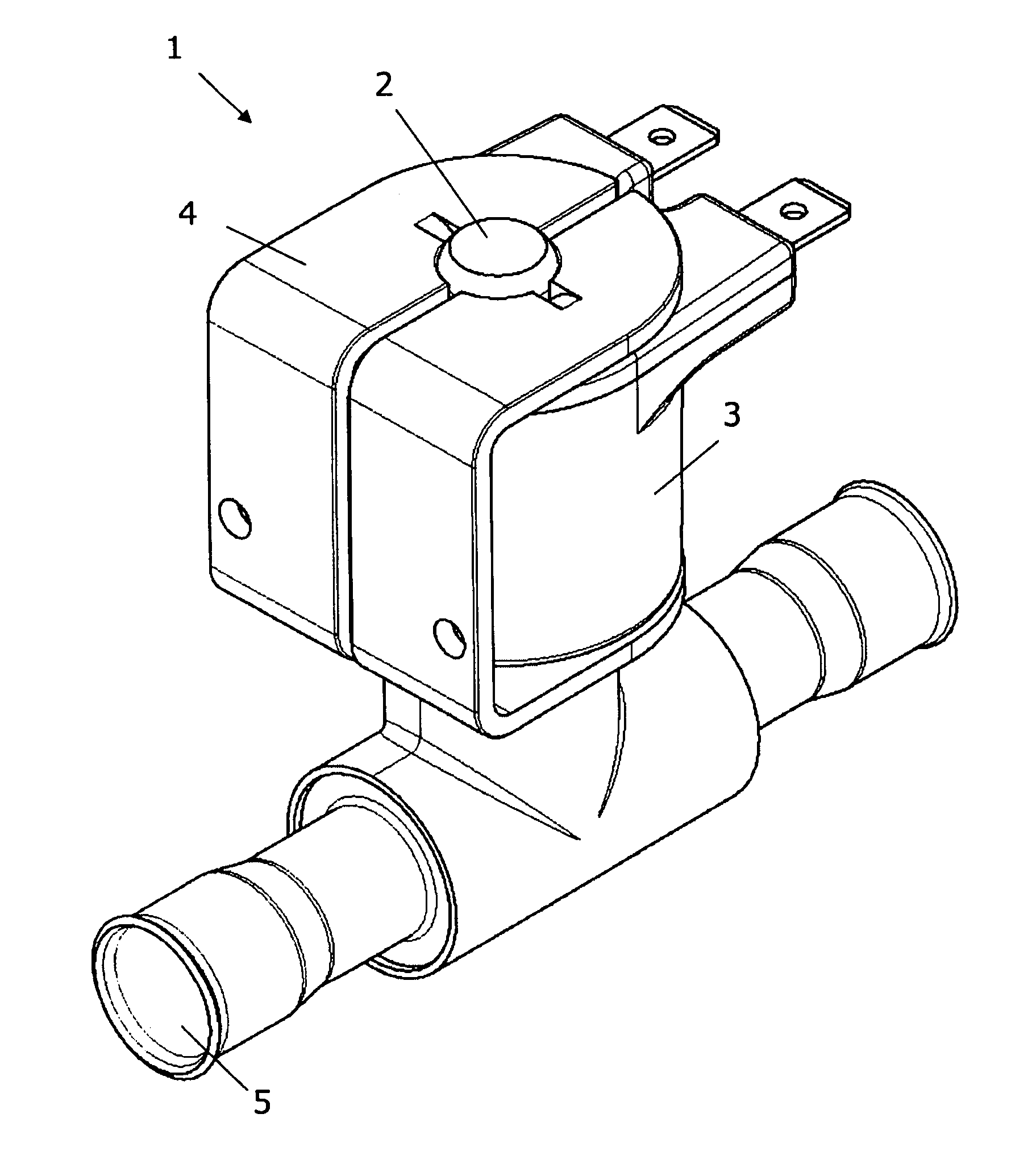
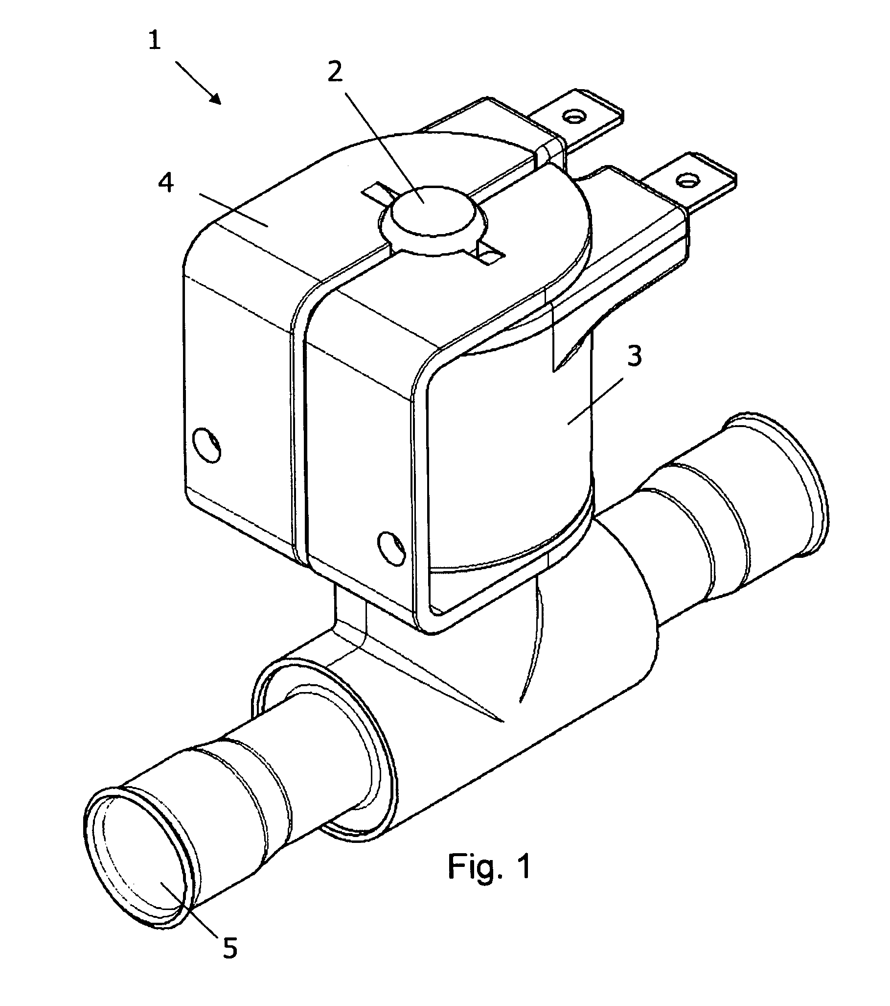
[0042]FIGS. 1-4 illustrate an embodiment of the invention. The valve 1 comprises a tube 2 for guiding movement of a plunger (not shown) inside the tube 2. A solenoid 3 is arranged about the tube, and a yoke 4 is in an operational position relative to the tube 2 and solenoid 3.

[0043]The plunger operates a valve member which controls a flow through a flow conduit 5

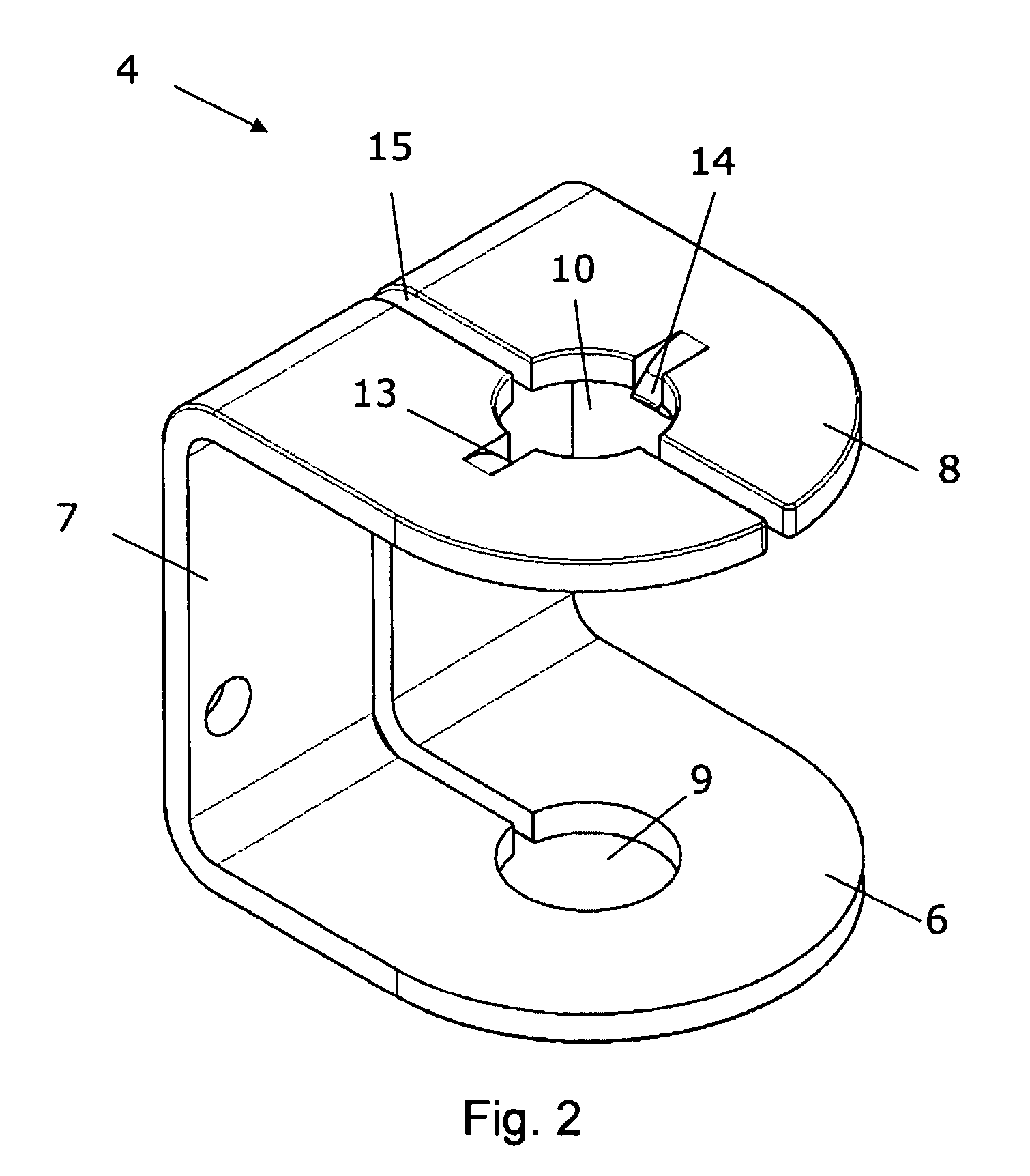
[0044]In FIG. 2, the yoke 4 is illustrated without the rest of the valve. The yoke comprises a lower leg 6, an intermediate portion 7 and an upper leg 8. Two openings 9, 10 formed as through holes, and they are aligned so that they form a passage for the tube 2. When the solenoid is arranged between the two legs 6, 8, and the tube is arranged in the passage through the openings 9, 10, the yoke 4 provides a magnetic path between the solenoid 3 and portions of the tube. The solenoid forms a passage which, in the operational position, is in line with the passage formed by the openings 9, 10 in the yoke 4 so that the tube 2 can ...


PUM

PropertyMeasurementUnit
elastic propertiesaaaaaaaaaa
elastic deformationaaaaaaaaaa
electricallyaaaaaaaaaa

Abstract

The invention provides a valve comprising a tube for guiding movement of a plunger, a solenoid which can be arranged about the tube, and a yoke which can be positioned in an operational position relative to the tube and relative to the solenoid so that it provides a magnetic path between the solenoid and portions of the tube. The yoke engages the tube and thereby prevents removal of the solenoid from tube. The invention thereby provides a very simple valve design with a low amount of components. The invention further provides a method of making a valve including fixing a solenoid to a tube by use of a yoke which engages the tube.

Description

CROSS REFERENCE TO RELATED APPLICATIONS[0001]This application is entitled to the benefit of and incorporates by reference essential subject matter disclosed in International Patent Application No. PCT / DK2010 / 000004 filed on Jan. 11, 2010 and Danish Patent Application No. PA 2009 00051 filed Jan. 13, 2009.FIELD OF THE INVENTION[0002]The present invention relates to a valve comprising a tube for guiding movement of a plunger, a solenoid which can be arranged about the tube, and a yoke which can be positioned in an operational position relative to the tube and relative to the solenoid so that it provides a magnetic path between the solenoid and end-portions of the tube.BACKGROUND OF THE INVENTION[0003]In valves of the above mentioned kind, the plunger, sometimes referred to as an armature, interacts with a closure member which controls fluid flow in a flow path through the valve. The valve is therefore electrically operable via the solenoid arranged about the tube.[0004]An electromagne...

Claims


Application Information

Patent Timeline
Patent Type & Authority Patents(United States)
IPC IPC(8): F16K31/02
CPCF16K31/0675H01F7/127Y10T29/49405
Inventor CHRISTENSEN, OLE, HOLST
Owner DANFOSS AS
Why Eureka
Try Eureka