Stainless steel composite and manufacturing method thereof

a technology of steel composite and manufacturing method, which is applied in the field of composites, can solve the problems of difficult to achieve the roughness of covering the entire surface, difficult to pull away, and difficult to catch resin on fine irregularities, etc., and achieves the effect of easy manufacturing, easy manufacturing, and easy production of large and/or elongated frp products

Inactive Publication Date: 2010-05-13
TAISEI PLAS CO LTD
View PDF10 Cites 8 Cited by
  • Summary
  • Abstract
  • Description
  • Claims
  • Application Information

AI Technical Summary

Benefits of technology

[0084]FIG. 5 illustrates an example of the use of CFRP in which stainless steel thin plates are bonded to the front and rear faces of a flat plate-like CFRP. A composite plate material 26 has a three-layer structure in which a CFRP 27 is laminated as a core layer, and stainless steel thin plates 28 are bonded to the front and rear faces of the CFRP 27. Through-holes 29 are opened in the composite plate material 26. Bolts 30 are inserted through the through-holes 29. The bolts 30 run also through angle members 31, having an L-shaped cross section, disposed below the composite plate material 26. The bolts 30 are screwed into nuts (not shown), disposed on the underside of the angle members 31. As a result, the composite plate material 26 and the angle members 31 make up a single structure. The stainless steel plates 28 are bonded to the front and rear faces of the CFRP 27, and hence the CFRP 27 is not damaged on account of, for instance, the fastening pressure exerted by the fastening bolts 30, or through friction with the bolts 30. The composite plate material 26, therefore, brings out the characteristics of both the CFRP 27 and the stainless steel thin plates 28, and can thus make up a structure that is lightweight and mechanically strong.
[0085]As explained in detail above, the stainless steel composite and manufacturing method thereof of the present invention allow providing, for instance, tough parts and structures in wh

Problems solved by technology

Causing such roughness to cover the entire surface is difficult to achieve in practice by relying on chemical treatments where variability is a concern.
As a result, the resin catches onto the fine irregularities and is difficult to pull away when a pulling force acts from the resin side.
Specifically, the reaction of the hypothesis is a high-rate reaction at high temperature and under high pressure, and thus cannot be measured directly.
On closer inspection, however, metal surface treatment methods such as phosphoric acid treatment, chromate treatment and anodization rely still on staple treatment methods developed 40 or more years a

Method used


Image

  • Stainless steel composite and manufacturing method thereof
  • Stainless steel composite and manufacturing method thereof
  • Stainless steel composite and manufacturing method thereof

Examples


experimental example 1

Stainless Steel and Adhesive

[0104]A 1-mm thick plate material of commercial stainless steel SUS316 was procured, and was cut into 45 mm×18 mm rectangular pieces. A degreasing aqueous solution was prepared in a dipping bath by heating, at a temperature of 60° C., an aqueous solution containing 7.5% of a commercially available degreasing agent “NE-6 (by Meltex, Tokyo, Japan)” for aluminum alloys. The stainless steel plate material was immersed for 5 minutes in the above aqueous solution, followed by thorough rinsing with water. Next, the stainless steel plate material was immersed for 1 minute in another dipping bath, having a 1.5% aqueous solution of caustic soda at 40° C., and was thoroughly rinsed with water thereafter. Treatment with a basic aqueous solution, though not essential, is a preliminary basic treatment previous to the subsequent treatment with sulfuric acid. This preliminary basic treatment results in a stable subsequent acid treatment. A 10% aqueous solution of 98% sul...

experimental example 2

Stainless Steel and Adhesive

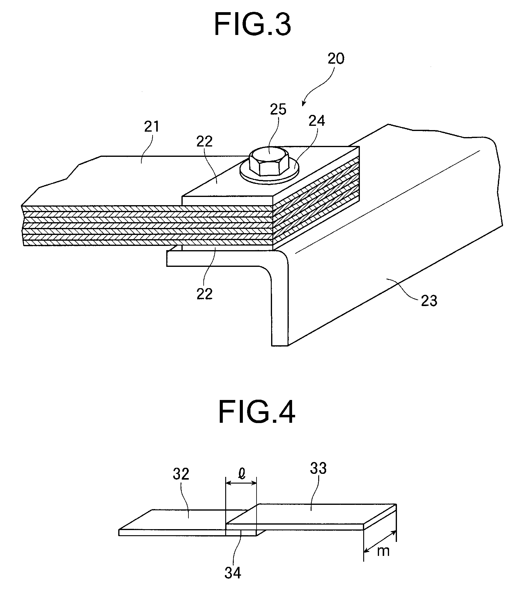
[0108]Exactly the same experiment as in experimental example 1 was carried out using a 1 mm-thick plate material of stainless steel SUS316, but modifying the immersion time in the aqueous solution of sulfuric acid from 3 minutes to 6 minutes. Otherwise, the procedure was exactly the same as in experimental example 1. A tensile fracture test of the obtained integrated product illustrated in FIG. 4 yielded a shear fracture strength, averaged over four sets, of 56 MPa. That is, the pieces were bonded yet more strongly than in experimental example 1.

experimental example 3

Stainless Steel and Adhesive

[0109]A 1-mm thick plate material of commercial stainless steel SUS304 was procured, and was cut into 45 mm×18 mm rectangular pieces. A degreasing aqueous solution was prepared in a dipping bath by heating, to a temperature of 60° C., an aqueous solution containing 7.5% of a commercially available degreasing agent “NE-6 (by Cemedine)” for aluminum alloys. The stainless steel plate material was immersed for 5 minutes in this degreasing agent aqueous solution, followed by thorough rinsing with water. Next, the stainless steel plate material was immersed for 1 minute in another dipping bath of a 1.5% aqueous solution of caustic soda at 40° C., and was rinsed with water thereafter. A 10% aqueous solution of 98% sulfuric acid was prepared next at 65° C. The stainless steel plate pieces were immersed for 3 minutes in the aqueous solution, and were then thoroughly rinsed with deionized water. The pieces were then immersed for 3 minutes in a 3% aqueous solution o...


PUM

PropertyMeasurementUnit
Temperatureaaaaaaaaaa
Percent by massaaaaaaaaaa

Abstract

A CFRP-integrated stainless steel complex used for a hydrogen containing tank, a food processing machine, a medical device, a general-purpose machine, and other machines can be designed as a further rational design product with a smaller weight. It has been found that a stainless steel material (22) having particular ultra-micro convex/concave shapes exhibits an excellent adhesive force in combination with an epoxy resin adhesive agent. By using the technique, a stainless steel thick plate piece (22) is used as a cover material in combination with a CFRP (21) to obtain a stainless steel complex (20). This can be assembled with other metal member by tightening bolts. Moreover, by using the excellent adhesive force, it is possible to easily create a structure member having a main portion of CFRP (21) and an end portion of metal. This can be easily assembled with and disassembled from other part by using bolts/nuts and screws.

Description

TECHNICAL FIELD[0001]The present invention relates to a composite of, for instance, stainless steel and stainless steel, stainless steel and another metal alloy, or stainless steel and a fiber-reinforced plastic, as used in industrial machinery such as transport equipment, electric equipment, medical equipment or general machinery, as well as in consumer appliances. The invention relates also to a joining method of such a composite. More particularly, the present invention relates to a stainless steel composite and a manufacturing method thereof, the stainless steel composite employing both a fiber-reinforced plastic (hereafter, FRP) and a stainless steel used in hydrogen storage tanks, food processing machinery, medical equipment, general machinery and other machinery, the stainless steel composite also being employed in parts, chassis, bodies and the like of various devices, machinery and systems.BACKGROUND ART[0002]Technologies for integrating metals with resins are required in a...

Claims


Application Information

Patent Timeline
IPC IPC(8): B32B15/092C09J5/02C09J163/00B23P17/00
CPCB32B15/08C08G59/4021C09J163/00Y10T29/49986C23F1/28C08L2666/04B32B5/147B32B7/12B32B15/06B32B15/092B32B15/18B32B27/20B32B27/285B32B27/286B32B27/32B32B27/38B32B2262/0269B32B2262/101B32B2262/106B32B2264/101B32B2264/102B32B2264/104B32B2270/00B32B2307/714B32B2457/00B32B2535/00Y10T428/31522
Inventor NARITOMI, MASANORIANDOH, NAOKI
Owner TAISEI PLAS CO LTD
Why Eureka
Try Eureka