

Method and system for validating video apparatus in an active environment
- Summary
- Abstract
- Description
- Claims
- Application Information
AI Technical Summary
Benefits of technology
Problems solved by technology
Method used
Image

Examples
Embodiment Construction
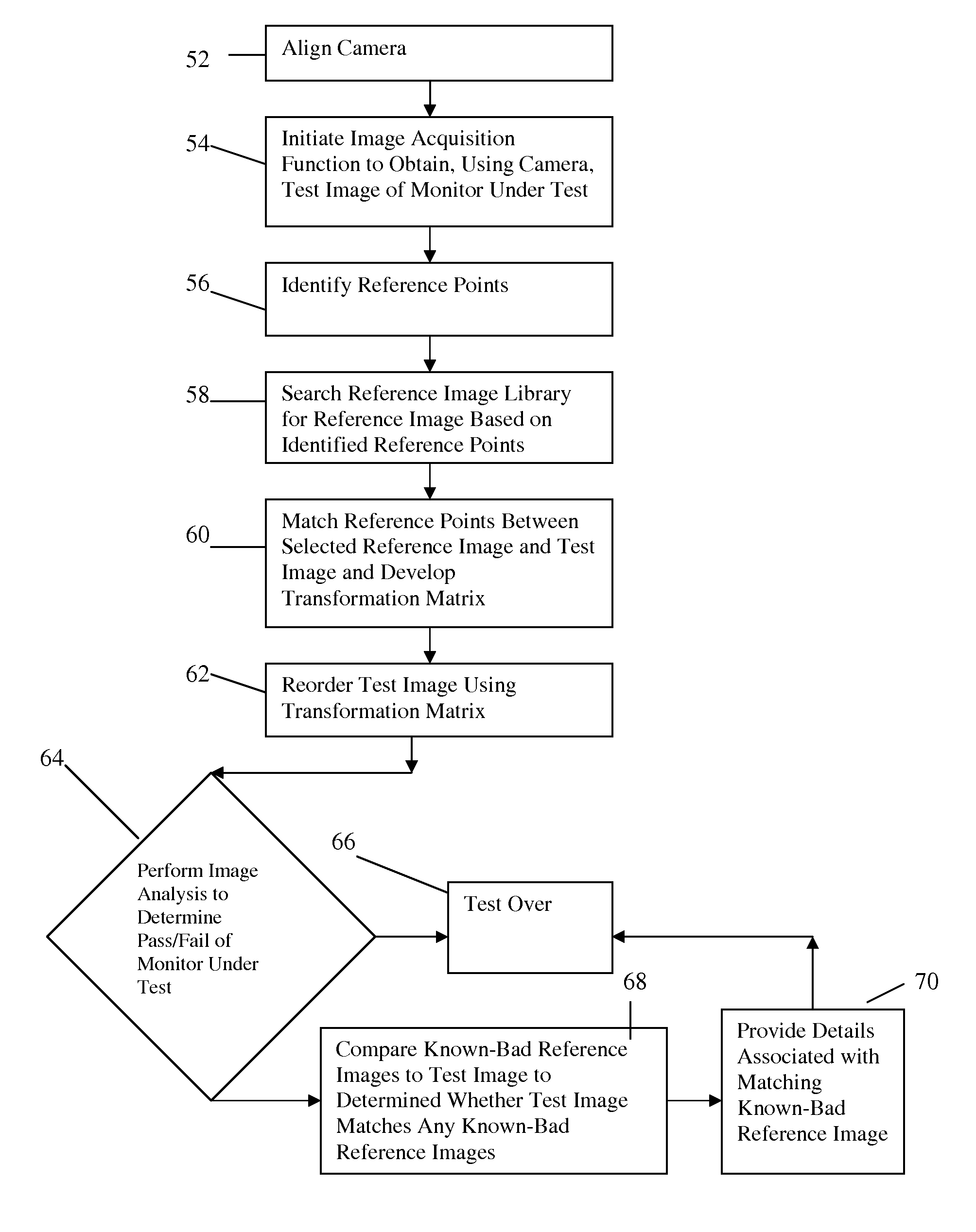
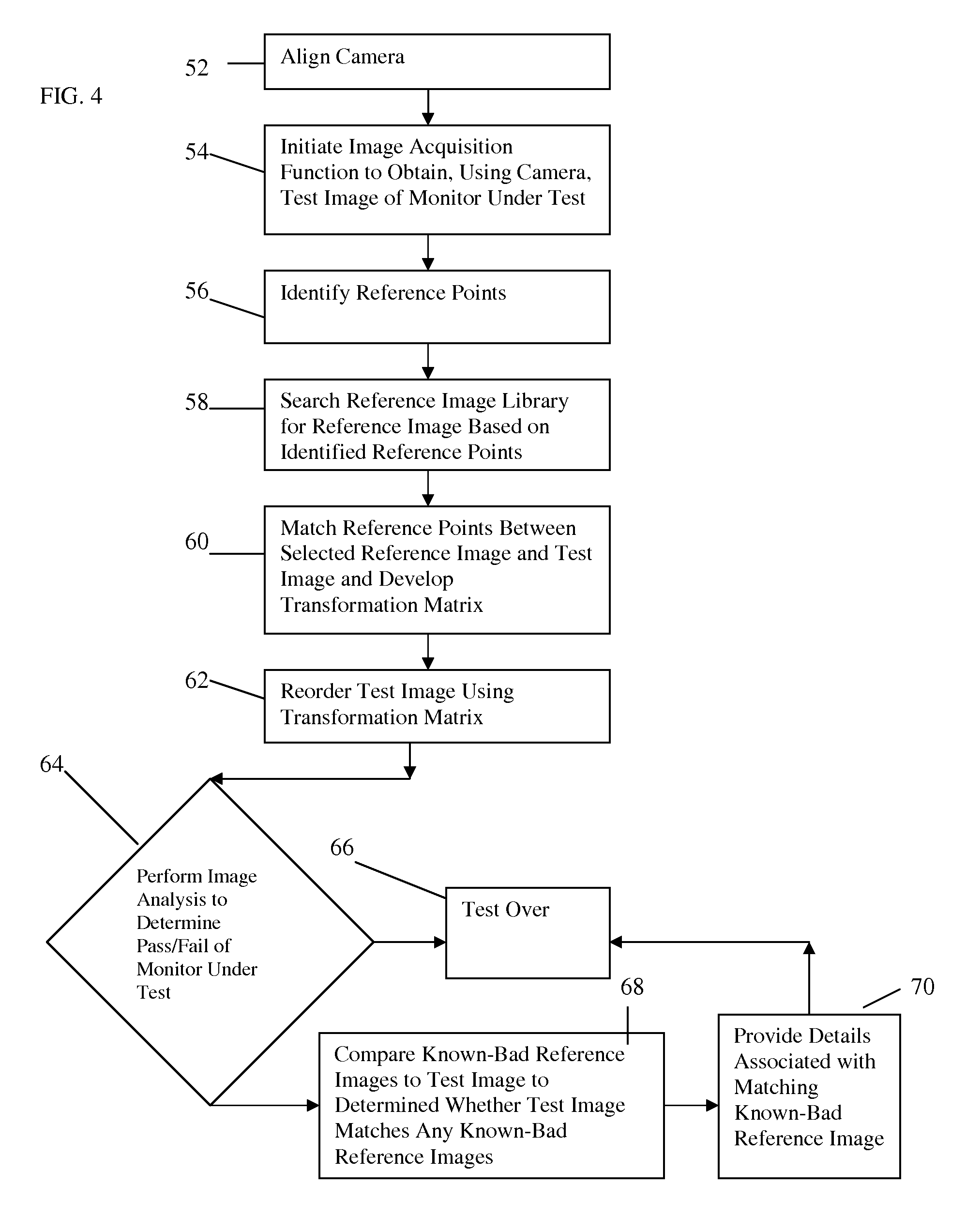
[0020]For the purposes of the following description, reference will be made to a ‘cockpit’ as the location where the invention will be performing its primary function. This terminology is used to illustrate an exemplifying application of the method and system in accordance with the invention within an applicable environment in which the equipment to be tested is mounted and is not intended to limit the scope of this invention in any way.
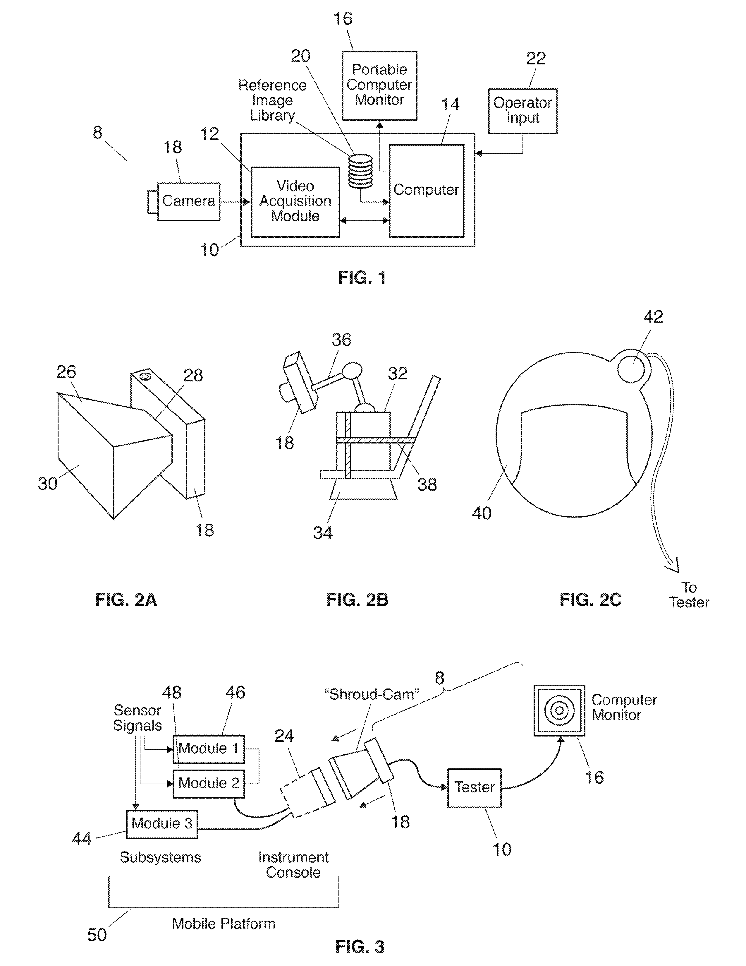
[0021]Referring to the accompanying drawings wherein the same reference numerals refer to the same or similar elements, a portable automatic video test analyzer in accordance with the invention is generally designated as 8 and generally includes either only partly or in its entirety, concepts from a Programmable Video Generator and Analyzer (PVGA / ePVGA), such as the type disclosed in the current assignee's U.S. Pat. No. 6,396,536 incorporated by reference herein in its entirety (shown in FIG. 1). In preferred embodiments, the video test analyzer 8 in...
PUM
 Abstract
Description
Claims
Application Information