Flexspline and wave gear device

a wave gear and flexspline technology, applied in the field of flexspline, can solve the problems of limitation and inability to increase the hollow diameter, and achieve the effect of increasing the hollow diameter more readily

a wave gear and flexspline technology, applied in the field of flexspline, can solve the problems of limitation and inability to increase the hollow diameter, and achieve the effect of increasing the hollow diameter more readily

US8646360B2Active Publication Date: 2014-02-11HARMONIC DRIVE SYST IND CO LTD

Image

  • Flexspline and wave gear device
  • Flexspline and wave gear device
  • Flexspline and wave gear device

Examples


Embodiment Construction

[0041]Embodiments of a flexspline and wave gear device to which the present invention is applied are described below with reference to the accompanying drawings

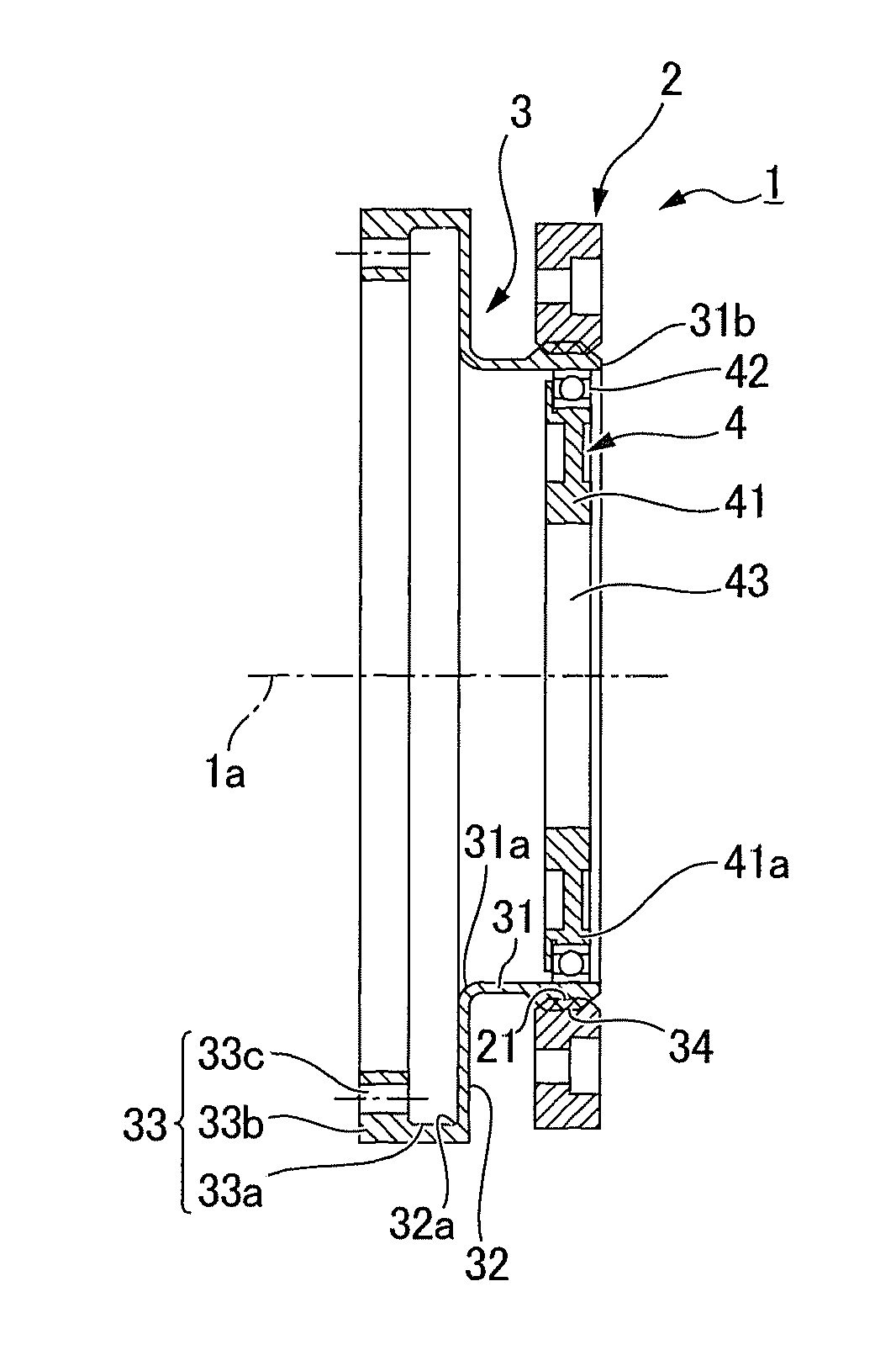
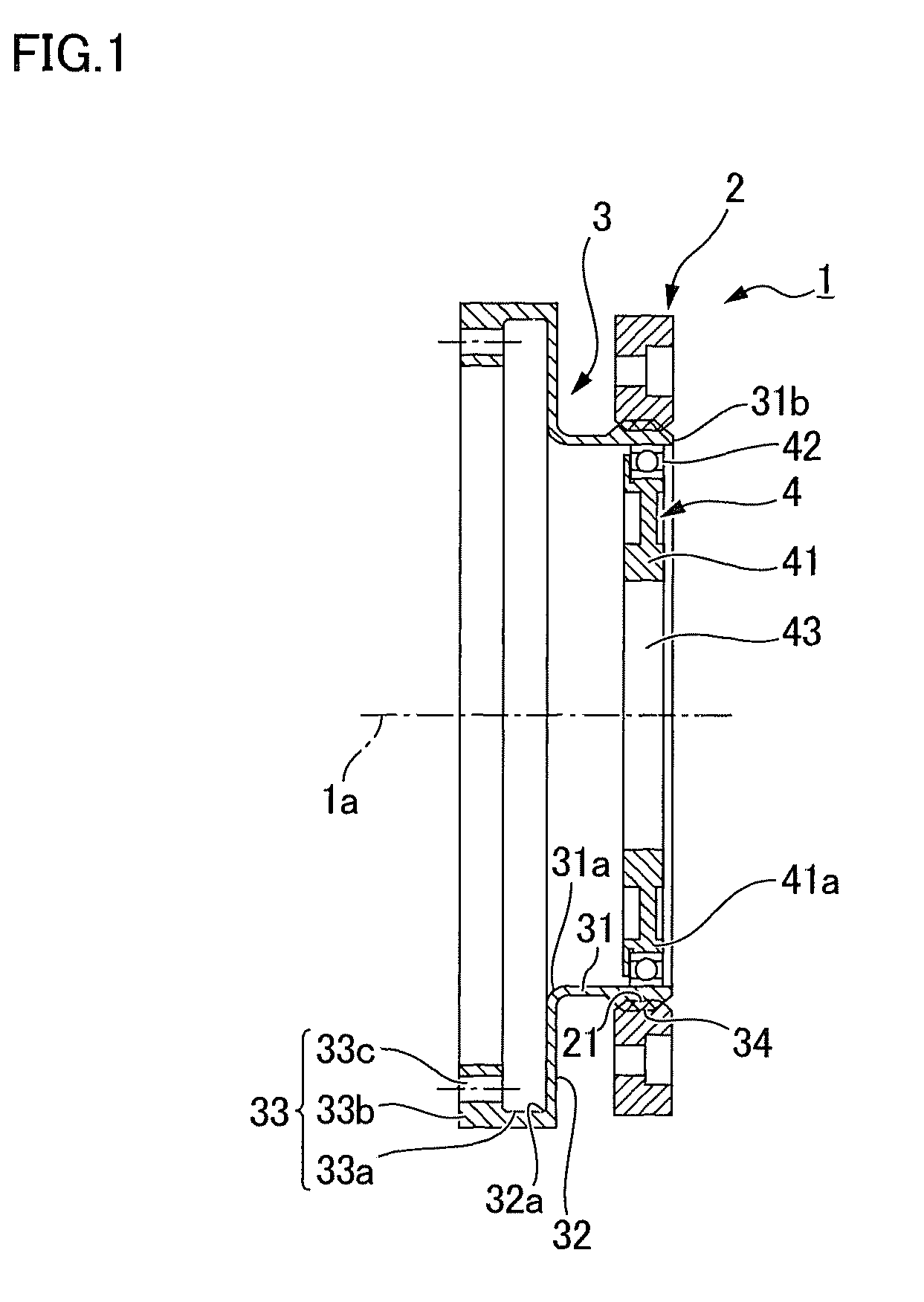
[0042]FIG. 1 is a longitudinal cross-section showing one example of a hollow wave gear device to which the present invention is applied A wave gear device 1 comprises a rigid circular spline 2; a flexspline 3; and an elliptical, hollow wave generator 4.

[0043]Internal teeth 21 are formed on an inner peripheral surface of the circular spline 2. The flexspline 3 is disposed inside the circular spline 2 in a coaxial state, the flexspline 3 comprising a radially flexible cylindrical body 31; a disc-shaped diaphragm 32 continuous with one open end 31a of the cylindrical body 31, the diaphragm 32 bending and extending outward in a radial direction; a rigid, annular flange 33 continuous with an outer peripheral edge 32a of the diaphragm 32; and external teeth 34 formed on an outer peripheral surface portion of the cylindrical body 31...


PUM


Abstract

In a flexspline of a wave gear device, an annular flange thereof is constructed from a first annular part bent at a right angle from an outer peripheral edge of a diaphragm, and a second annular part caused to inwardly protrude at a uniform width from a leading end of the first annular part. It is possible for the annular flange to be disposed within the region where the diaphragm is formed, as viewed in the direction of an axis of the device. An outer diameter can be reduced to a greater extent than with a “silk hat”-shaped flexspline; and when a hollow wave gear device is manufactured, a hollow diameter can be more readily increased than in a case where a cup-shaped flexspline is used.

Description

TECHNICAL FIELD[0001]The present invention relates to a flexspline that is a component of a wave gear device, and particularly relates to an improvement to a flexspline shape making it possible to reduce an outer diameter of a hollow wave gear device.BACKGROUND ART[0002]Wave gear devices are typically known to be of a cup type, which has a cup-shaped flexspline (see Patent Document 1); a “silk hat” type, which has a flexspline having a shape resembling a top hat (see Patent Document 2); and a flat type, which has a cylindrical flexspline (see Patent Document 3). In the cup type and the “silk hat” type, an attachment flange or boss is formed on the flexspline. The flange or boss is a rigid member and is shaped like a disc or a ring. A stationary-side member or a load-side member is securely coupled to the flange or boss.[0003]When a cup type hollow wave gear device having a hollow part penetrating and extending through the center is used, the attachment flange, which defines the bott...

Claims


Application Information

Patent Timeline
11 Feb 2014
Publication
US8646360B2
IPC
F16H49/00; F16H1/32
CPC
F16H49/001; F16H2049/003; Y10T74/1987; Y10T74/19
Inventors
KANAI, SATORU