Gas storage canister with compartment structure

a technology of gas storage canisters and compartments, which is applied in the direction of electrochemical generators, transportation and packaging, and packaging goods types, etc., can solve the problems of unsatisfactory methods, deterioration of the efficiency of releasing gas (e.g. hydrogen gas) from gas storage materials, and failure to uniformly and stably heat gas storage materials, etc., to achieve enhanced operating efficacy and structural strength of the housing, the effect of uniform outpu

Active Publication Date: 2014-02-11
ASIA PACIFIC FUEL CELL TECH
View PDF35 Cites 16 Cited by
  • Summary
  • Abstract
  • Description
  • Claims
  • Application Information

AI Technical Summary

Benefits of technology

[0006]The present invention also provides a gas storage canister for storing the gas storage material, in which the partition articles for accommodating the gas storage material has enhanced structural strength and tightness.
[0011]By means of the present technology, a predetermined amount of gas storage material is accommodated within the compartment of the compartment structure, so that the gas storage material is locally distributed. Consequently, during operation of the fuel cell system, the gas storage canister allows the external heat to be uniformly conducted to the compartments of all compartment structures. Since the heat applied to the inner portion and the outer portion of the gas storage material are not obviously distinguished during the heating stage, the released gas can be outputted more uniformly and stably. Under this circumstance, the operating efficacy of the present invention is enhanced. Moreover, since the compartment structure is accommodated within the receptacle of the housing and the partition plate is effective to reinforce the structural strength of the housing, the operation of the gas storage canister is more stable, and the working efficiency of the fuel cell system is enhanced. In such way, a gas storage cartridge is modularized to facilitate production, assembly and application, so that the industrial utilization is enhanced.

Problems solved by technology

Since the gas storage material is usually in a powdery form and the gas storage material is accommodated within a single receptacle of the canister body, if the volume of the gas storage material is too large, the gas storage material fails to be uniformly and stably heated.
Under this circumstance, the efficiency of releasing the gas (e.g. the hydrogen gas) from the gas storage material is deteriorated.
Unfortunately, these methods are unsatisfied because the thermal expansion of the gas storage material may result in deformation of the partition articles.
Under this circumstance, the gas storage material may be leaked to and stacked over other partition layers or a non-uniform heating problem occurs, so that the performance of the gas storage canister is impaired.

Method used


Image

  • Gas storage canister with compartment structure
  • Gas storage canister with compartment structure
  • Gas storage canister with compartment structure

Examples


first embodiment

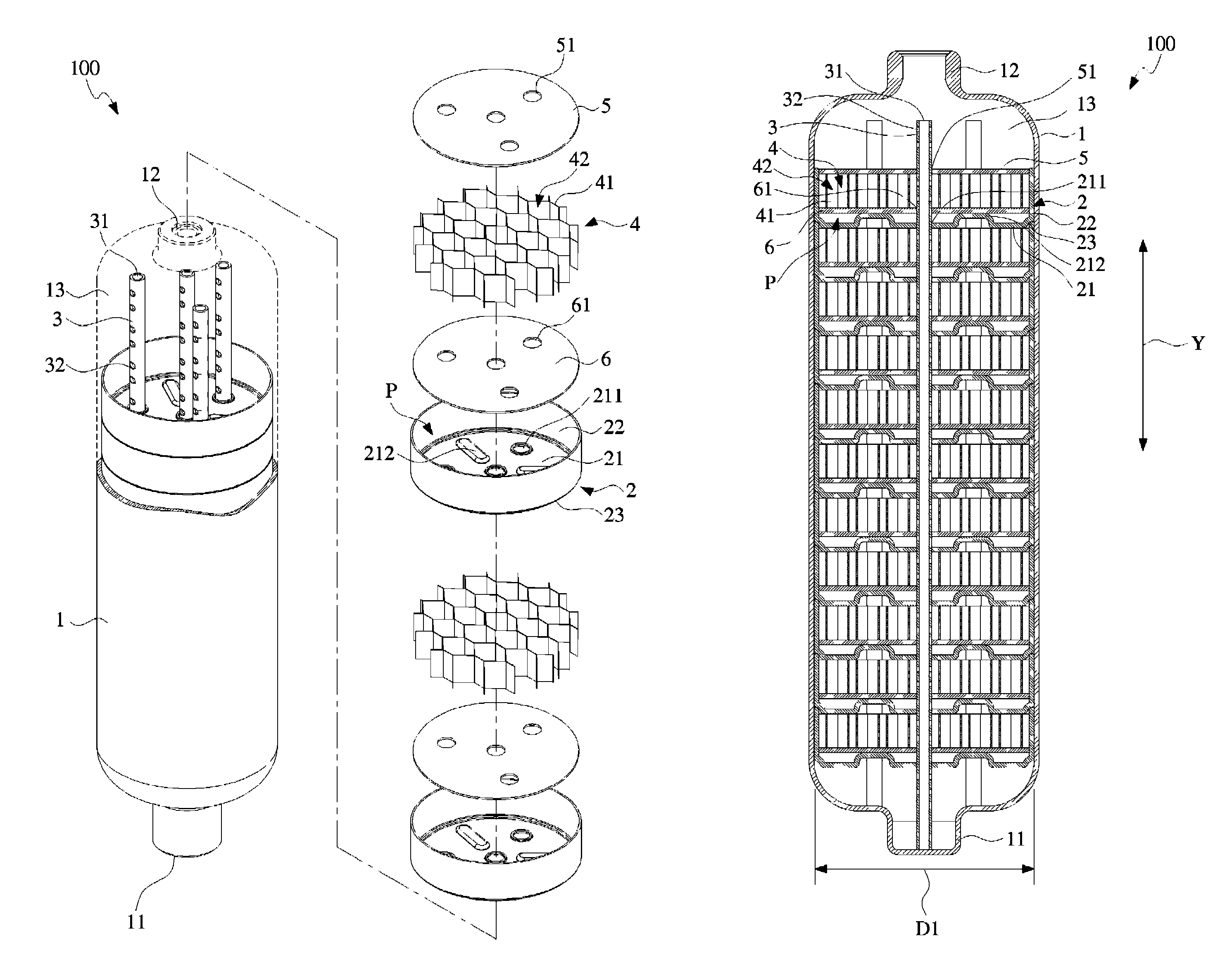
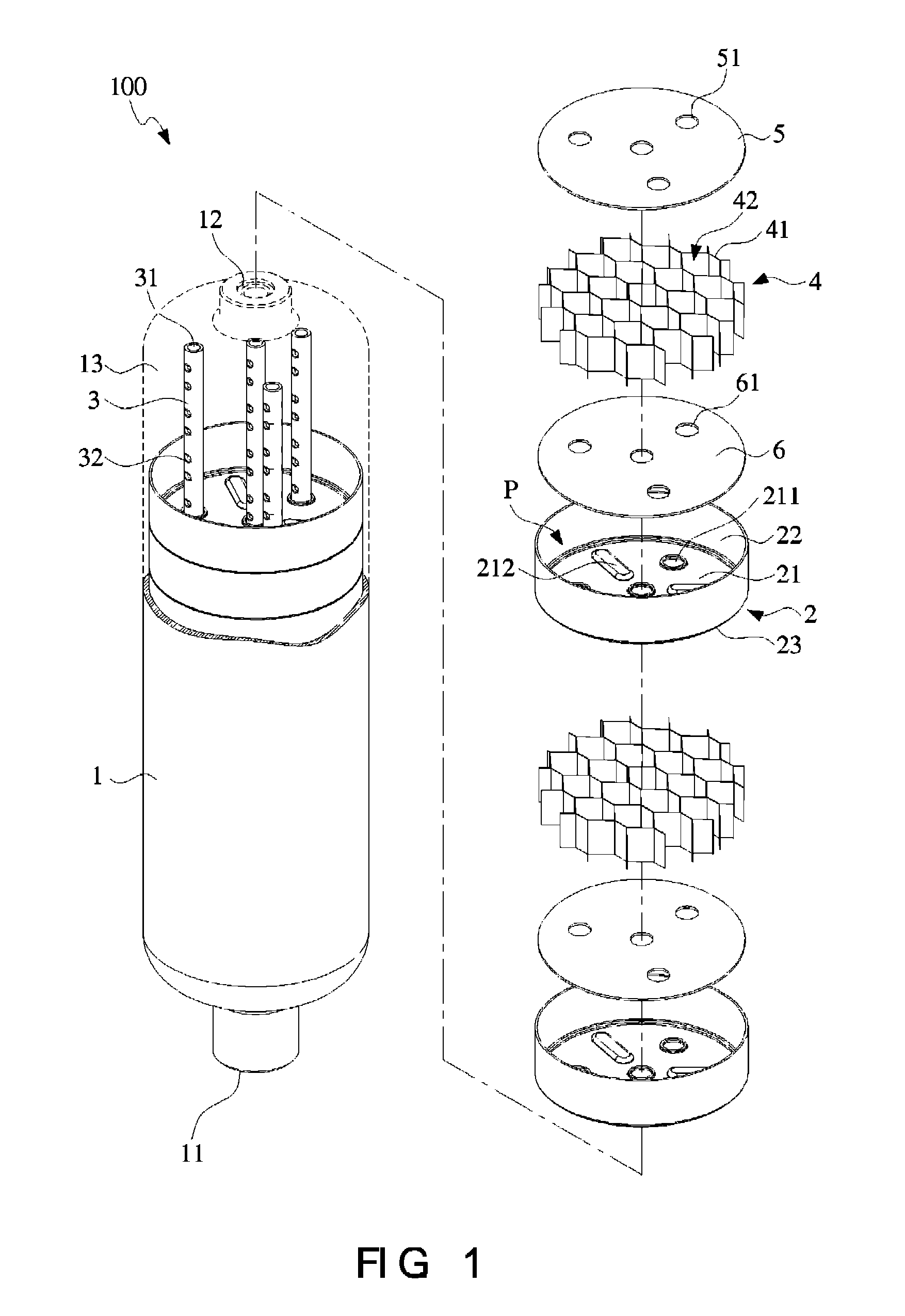
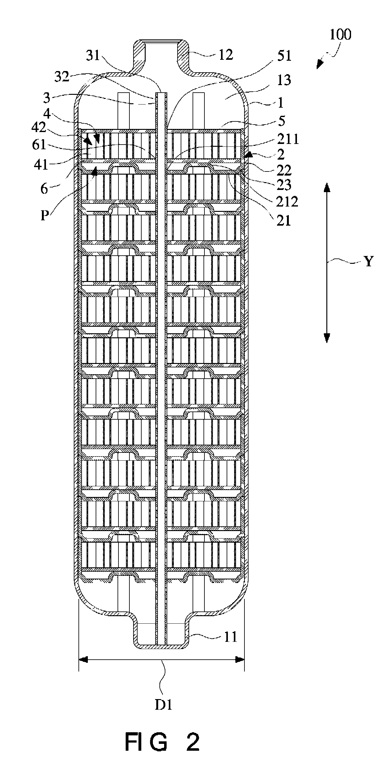
[0036]FIG. 3 is a schematic perspective view illustrating a housing of the gas storage canister according to the present invention. FIG. 4 is a schematic perspective view illustrating the housing of FIG. 3 and taken along another viewpoint. Please refer to FIGS. 1, 2, 3 and 4. The canister body 1 has an inner diameter D1. The housing 2 has an outer diameter D2. The inner diameter D1 of the canister body 1 is substantially equal to the outer diameter D2 of the housing 2. After the housing 2 is accommodated within the inner space 13 of the canister body 1, the peripheral wall 22 of the housing 2 and the inner wall of the canister body 1 are in contact with each other. In this embodiment, a concave ring-shaped edge structure 23 is formed at a junction between the base 21 and the peripheral wall 22 of the housing 2. After the plurality of housings 2 are accommodated within the inner space 13 of the canister body 1, every two adjacent housings 2 are engaged with each other through the pe...

third embodiment

[0043]FIG. 11 is a schematic cross-sectional view illustrating the gas storage canister of FIG. 10 and taken along the line 11-11. As shown in FIG. 11, the gas-conducting structure 24 comprises a tube structure 241 and a filtering layer 242. The tube structure 241 is vertically and upwardly extended from the aperture wall of the communication part 211 of the housing 2 by a predetermined height L. In addition, the tube structure 241 has at least one vent 243 for conducting the gas. The filtering layer 242 is sheathed around the tube structure 241 for preventing the gas storage material from being leaked out to other housing 2 through the communication part 211. In this embodiment, the predetermined height L is substantially equal to the distance between the base 21 of the housing 2a and the cover 5. That is, the communication part 211 of the housing 2 and the first opening 51 of the cover 5 corresponding to the gas-conducting structure 24 are sealed by the gas-conducting structure 24...

fifth embodiment

[0046]FIG. 15 is a schematic exploded view illustrating a gas storage cartridge of the gas storage canister according to the present invention. In the gas storage canister 200b, at least one gas-conducting structure 25 is formed on the peripheral wall 22 of the housing 2b. Through the gas-conducting structures 25, the gas can be introduced to and adsorbed by the gas storage material, which is accommodated within the housings 2b. In addition, through the gas-conducting structures 25, the gas released from the gas storage material is guided to the outlet 12 of the canister body 1. In this embodiment, the cover 5a has at least one notch 52 corresponding to the gas-conducting structure 25 of the housing 2b. Consequently, after the gas storage canisters 200b are stacked over each other, the gas can be conducted through the notch 52. Alternatively, the cover 5a has a vertical and downward edge with a predetermined height for facilitating coupling the cover 5a with the housing 2b. The gas ...


PUM

PropertyMeasurementUnit
chemical energyaaaaaaaaaa
energyaaaaaaaaaa
volumeaaaaaaaaaa

Abstract

A gas storage canister includes a canister body, at least one supporting plate, at least one gas-guiding rod, and at least one compartment structure. The canister body has a bottom end, an outlet opposed to the bottom end, and an inner space. The bottom end and the outlet are arranged along a long axis direction. The supporting plate is accommodated within the inner space along the long axis direction. The supporting plate has at least one communication part. The gas-guiding rod is penetrated through the communication part of the supporting plate. The gas-guiding rod has at least one gas inlet / outlet end for guiding a gas. The compartment structure includes a plurality of compartments. The compartment structure and the supporting plate are accommodated within the inner space of the canister body. Each of the compartments stores a predetermined amount of gas storage material.

Description

FIELD OF THE INVENTION[0001]The present invention relates to a gas storage canister, and more particularly to a gas storage canister with a compartment structure or lattice.BACKGROUND OF THE INVENTION[0002]A fuel cell is a device that converts the chemical energy from a hydrogen-containing fuel into electricity through a chemical reaction with air. Consequently, the fuel cell is categorized as a new energy source. The hydrogen-containing fuel used in the fuel cell includes any type of hydrocarbon such as natural gas, methanol, ethanol (alcohol), product from water hydrolysis, marsh gas, or the like.[0003]The hydrogen gas is usually filled in a gas storage canister with metal hydride, so that the hydrogen gas is adsorbed and stored by the metal hydride. For using the hydrogen gas, the gas storage canister should be properly heated to release the hydrogen gas to the application device. Consequently, the fuel cell manufacturers make efforts in designing novel gas storage canisters for ...

Claims


Application Information

Patent Timeline
Patent Type & Authority Patents(United States)
IPC IPC(8): F17C1/02F17C11/00
CPCF17C1/14Y02E60/321F17C11/005F17C1/02Y02E60/32
Inventor YANG, JEFFERSON Y SLIAO, CHENG-HAMHSIAO, FENG-HSIANGKUO, TZU-WEI
Owner ASIA PACIFIC FUEL CELL TECH
Why Eureka
Try Eureka