Backlight module and display device thereof

a backlight module and display device technology, applied in the field of reflective plates, can solve the problems of increasing increasing the material cost as well as the overall weight of the product, and still many deficiencies of conventional displays, so as to reduce the reflection of light, improve the unevenness of light, and reduce the portion of reflection

Active Publication Date: 2014-02-11
AU OPTRONICS CORP
View PDF15 Cites 6 Cited by
  • Summary
  • Abstract
  • Description
  • Claims
  • Application Information

AI Technical Summary

Benefits of technology

[0011]The low reflection portions are disposed in the center of each lattice of the lattice pattern. Since light from the light source, through reflection from other optical components, is easily concentrated at the center to form bright spots, the present invention provides low reflection portions at the center to decrease the reflection of light, whereby eliminating the bright spots in order to improve the unevenness of light emanating from the display device.

Problems solved by technology

However, there are still many deficiencies with conventional displays using LEDs as light sources.
However, although this method shrinks the space between light sources 1D, the material cost as well as the overall weight of the product has also correspondingly increased as a consequence.
However, larger dimension displays (e.g. displays with dimensions greater than 71 inch) are not able to utilize diffuser plates 1B formed through ink printing methods.
As such, this method still does not overcome the mentioned bright spots problem.

Method used


Image

  • Backlight module and display device thereof
  • Backlight module and display device thereof
  • Backlight module and display device thereof

Examples


Embodiment Construction

[0024]A backlight module and a display device are provided to improve the phenomenon of light unevenness. In a embodiment, the backlight module is a light-emitting diode (LED) backlight module.

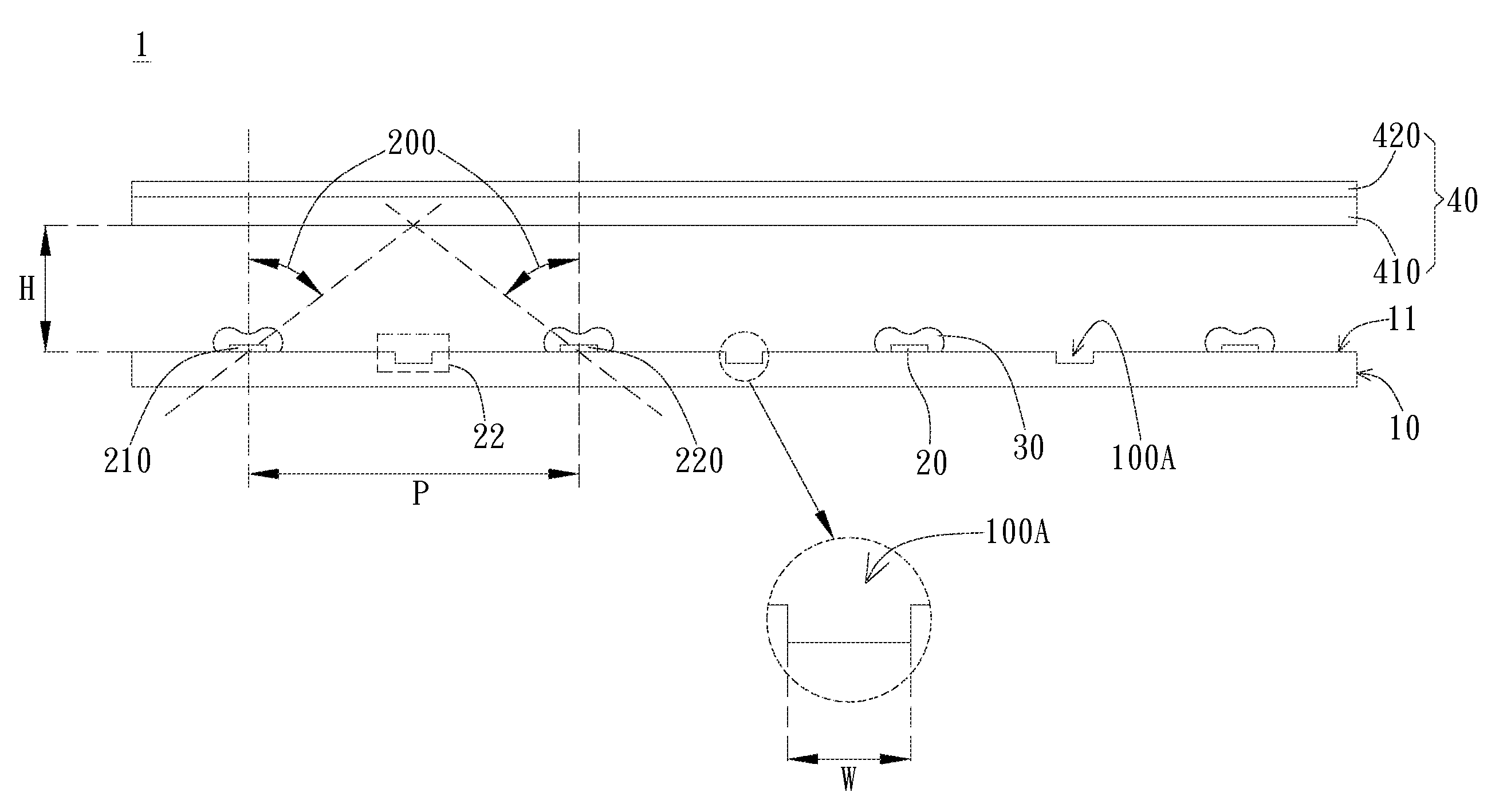
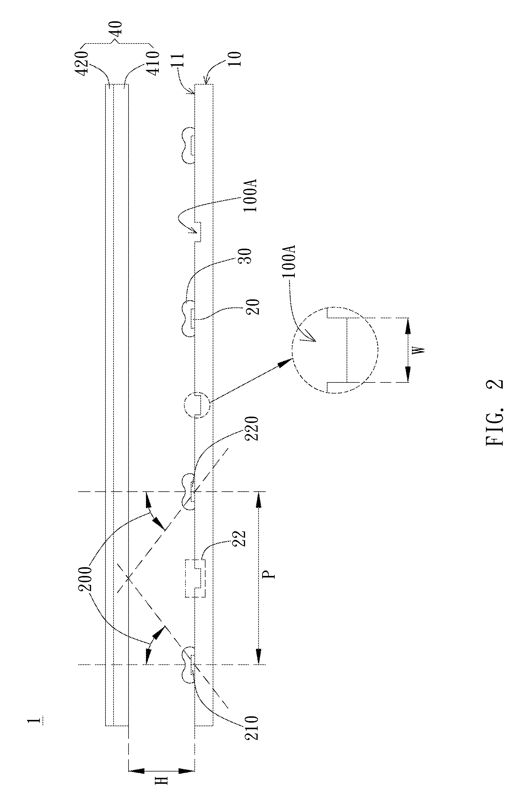
[0025]Referring to FIG. 2, FIG. 2 illustrates a side view of an embodiment of the backlight module. As shown in FIG. 2, the backlight module 1 includes the reflective plate 10 and a plurality of light sources 20, wherein the reflective plates 10 have reflective surfaces 11. The light sources 20 are disposed on the reflective surface 11, generating light in a direction away from the reflective surface 11. The reflective surface 11 includes a plurality of low reflection portions 100A, wherein the reflectivity of the low reflection portion 100A is lower than the reflectivity of other positions on the reflective surface 11 and the low reflection portion 100A is positioned within an area formed by the light source 20 and adjacent light sources 20. Specifically, the area formed by the light source 2...


PUM


Abstract

A backlight module and a display device including the backlight module are provided. The backlight module includes a reflective plate and a plurality of light sources, wherein the reflective plate has a reflective surface and the light sources are disposed on the reflective surface generating light in a direction away from the reflective surface. The reflecting surface includes a plurality of low reflection portions, wherein the reflectivity of the low reflection portion is lower than the reflectivity of other positions on the reflective surface. The low reflection portions are disposed between the light source and adjacent light sources.

Description

BACKGROUND[0001]1. Technical Field[0002]The present invention generally relates to a backlight module and a display device thereof. Particularly, the present invention relates to a reflective plate of a backlight module.[0003]2. Description of the Prior Art[0004]Technologies are being developed daily, with the optoelectronics industry continuously researching and developing greener and brighter lighting sources. For instance, light-emitting diodes (LED), which have advantages of saving energy while producing little heat, have become the common lighting source by replacing conventional lighting devices. LEDs are also being applied to various fields, such as flash lights, lamps, display devices, advertisement boards, as well as the outer walls of buildings. From this, it can be seen that LEDs are deeply entrenched in modern life. For example, liquid crystal displays utilizing backlights with LEDs have gradually become indispensible electronic products in households as they not only gr...

Claims


Application Information

Patent Timeline
Patent Type & Authority Patents(United States)
IPC IPC(8): G09F13/04
CPCG02F1/133605G02F1/133602G02F1/133606
Inventor SHEN, WEI-TAILIN, SU-YI
Owner AU OPTRONICS CORP
Why Eureka
Try Eureka