
Injection devices

Active Publication Date: 2014-02-11
OWEN MUMFORD
View PDF17 Cites 21 Cited by
  • Summary
  • Abstract
  • Description
  • Claims
  • Application Information

AI Technical Summary

Benefits of technology

The invention is an autoinjector device that can be easily operated with a weak grip or reduced dexterity. It has a mechanism that allows the user to adjust the depth of the injection by hand, which makes it easier to achieve and reduces the risk of slippage. The device includes a flexible element that can be pulled to activate it, and a mechanism that allows the user to adjust the depth of the injection by hand. This makes the device more user-friendly and easier to use.

Problems solved by technology

A problem with such devices is that, to ensure that there is sufficient stored energy in the device to effect these operations in a swift and reliable manner, a significant force has to be applied.
This is problematic for those who are weak or with reduced manual dexterity.
Also there is a risk that if the device slips during the cocking operation, injury could be caused.

Method used


Image

  • Injection devices
  • Injection devices
  • Injection devices

Examples


Embodiment Construction

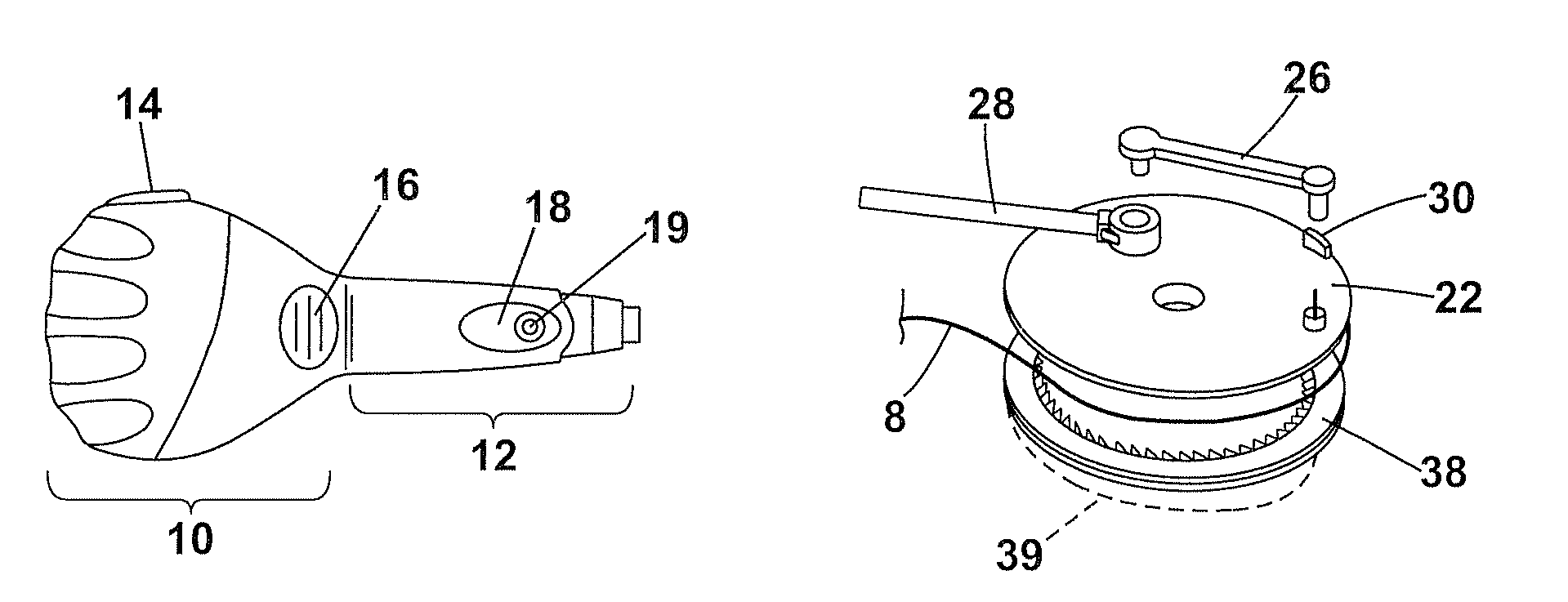
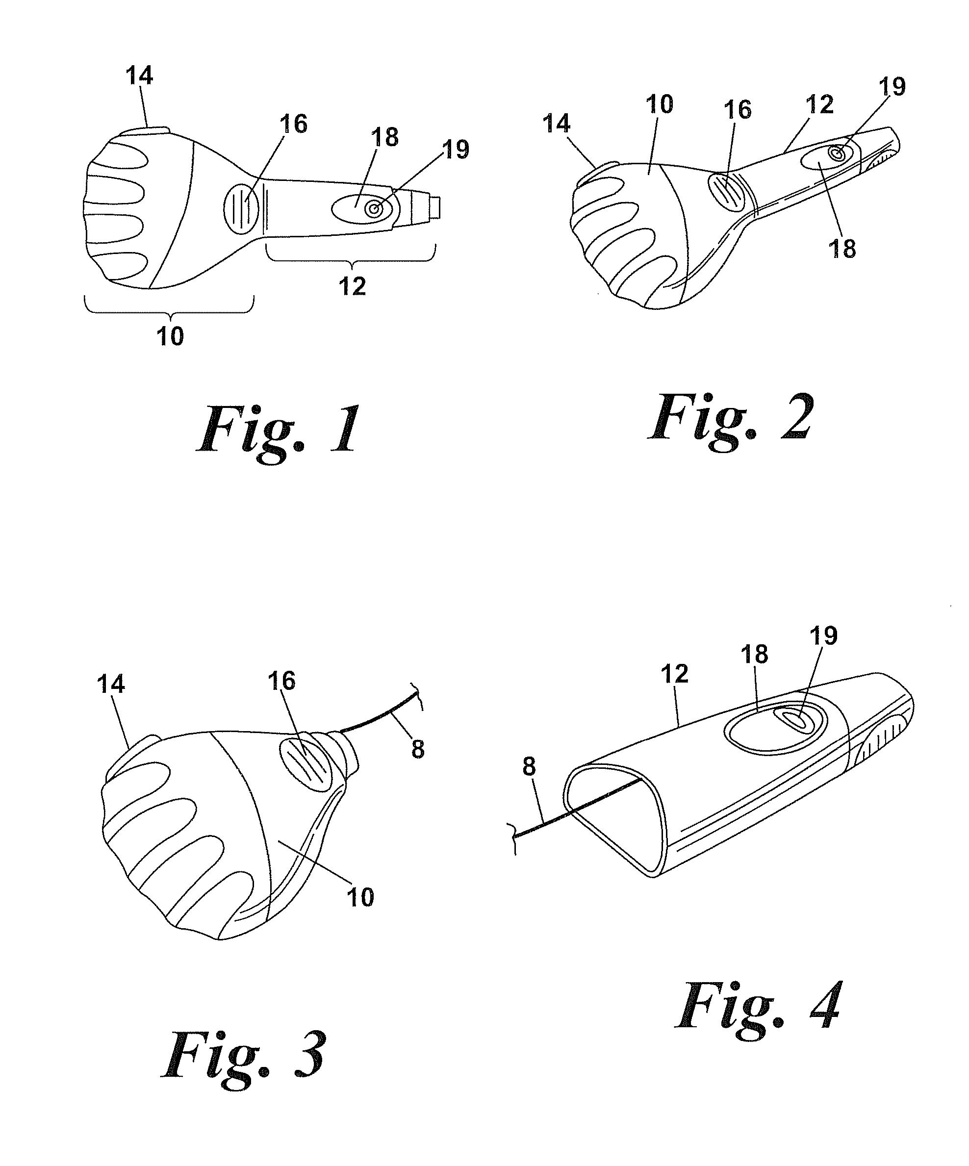
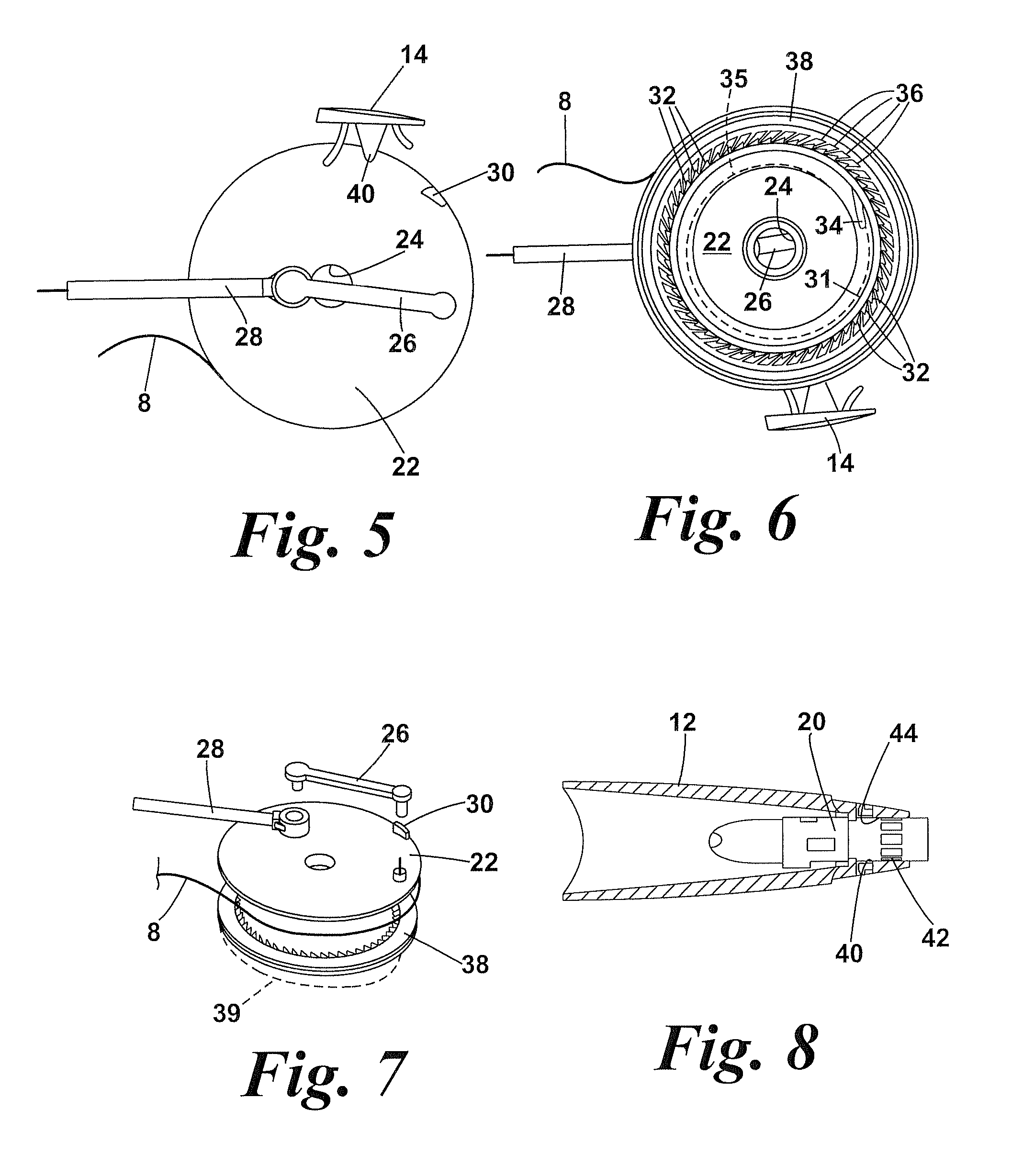
[0046]The device illustrated in the drawings is intended to allow easy autoinjection of a medicament from a disposable syringe which is fitted into the device. The device is intended to be “broken” into two separate parts to both allow insertion of the syringe into the syringe housing but also to allow the drive mechanism in the drive housing to be cocked by means of a cord 8 connected between the drive housing and the syringe housing.

[0047]The device comprises a drive housing 10 which houses the drive mechanism to be described below and which is shaped to fit easily in the palm of a user. A firing button 14 projects from the drive housing. The drive housing attaches to the syringe housing by a click fit which may be released by depressing two release buttons 16 on the drive housing. The syringe housing is provided with diametrically opposed penetration depth adjustment buttons 18 which are used as described below to adjust the amount of axial projection of a penetration depth colla...


PUM


Abstract

An autoinjector device comprises a drive housing 10 and a syringe housing 12 which can be disconnected to allow insertion of a syringe. A drive mechanism in the drive housing is cocked by means of a cord 8 connected between the drive housing and the syringe housing. The drive mechanism comprises a drive gear 22 rotatably mounted in the drive housing and acting as a rotary crank connected by a connecting rod 26 to a plunger 28. In use the drive gear 22 is driven by a torsion spring 35 so that the drive mechanism extends the syringe from the syringe housing and expels a dose and then retracts the syringe back into the housing. A firing button 14 releases the drive gear to be driven by the torsion spring but is also engageable as a brake on the rim of the drive gear.

Description

[0001]This invention relates to autoinjection devices and injection devices generally. In particular, but not exclusively, the invention is concerned with autoinjection devices which are designed for multiple use.[0002]Such devices may be used where it is required to autoinject on a regular basis a dose of medicament which is contained in a disposable syringe or a cartridge. In the majority of, if not all, such devices it is necessary to cock the drive mechanism of the device in some way to energise an energy storage device e.g. a spring. Once cocked, firing the drive mechanism causes the syringe or cartridge to be advanced so that the needle penetrates the skin of a user whereupon the dose is expelled. A problem with such devices is that, to ensure that there is sufficient stored energy in the device to effect these operations in a swift and reliable manner, a significant force has to be applied. This is problematic for those who are weak or with reduced manual dexterity. Also ther...

Claims


Application Information

Patent Timeline
IPC IPC(8): A61M5/20
CPCA61M2005/206A61M2005/2492A61M5/326A61M5/2033A61M5/482A61M5/24A61M5/20A61M2205/3334A61M2005/2407A61M2005/202A61M5/46
Inventor COWE, TOBY
Owner OWEN MUMFORD
Learn More