Multi-feed antenna for path optimization

Active Publication Date: 2014-02-11
KYOCERA AVX COMPONENTS (SAN DIEGO) INC
View PDF7 Cites 28 Cited by
  • Summary
  • Abstract
  • Description
  • Claims
  • Application Information

AI Technical Summary

Benefits of technology

[0014]In one embodiment, an IMD antenna including a single conductive structure having two feed ports is provided. The dual feed port IMD antenna is designed to operate at low frequencies at a first feed port, and to operate at high frequencies at a second feed port. Alternatively, the

Problems solved by technology

Another limitation of the prior art IMD structures includes the

Method used


Image

  • Multi-feed antenna for path optimization
  • Multi-feed antenna for path optimization
  • Multi-feed antenna for path optimization

Examples


Embodiment Construction

[0039]In the following description, for purposes of explanation and not limitation, details and descriptions are set forth in order to provide a thorough understanding of the present invention. However, it will be apparent to those skilled in the art that the present invention may be practiced in other embodiments that depart from these details and descriptions without departing from the spirit and scope of the invention. Certain embodiments will be described below with reference to the drawings wherein illustrative features are denoted by reference numerals.

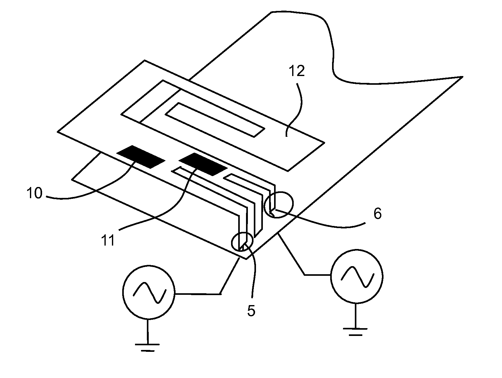
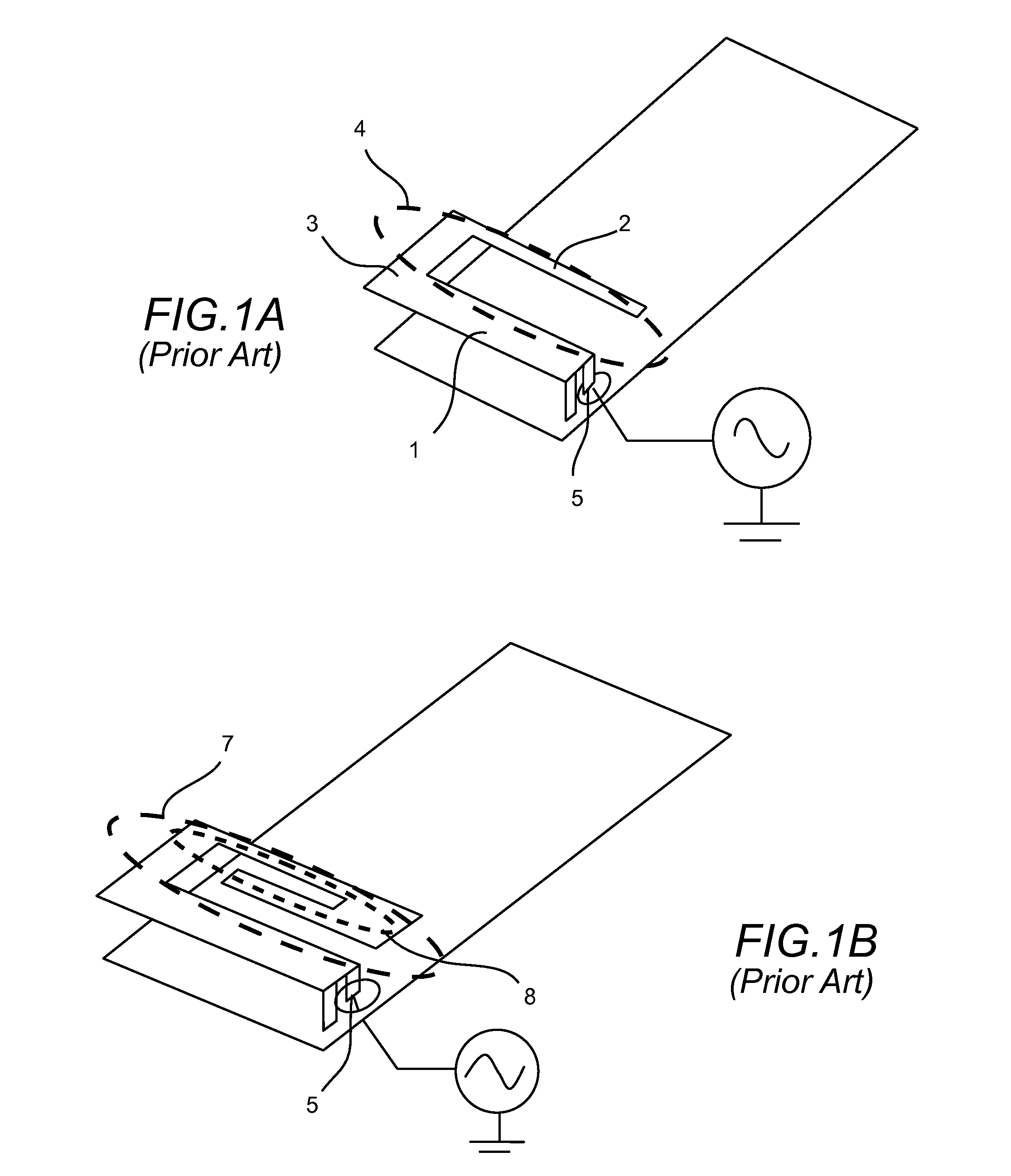
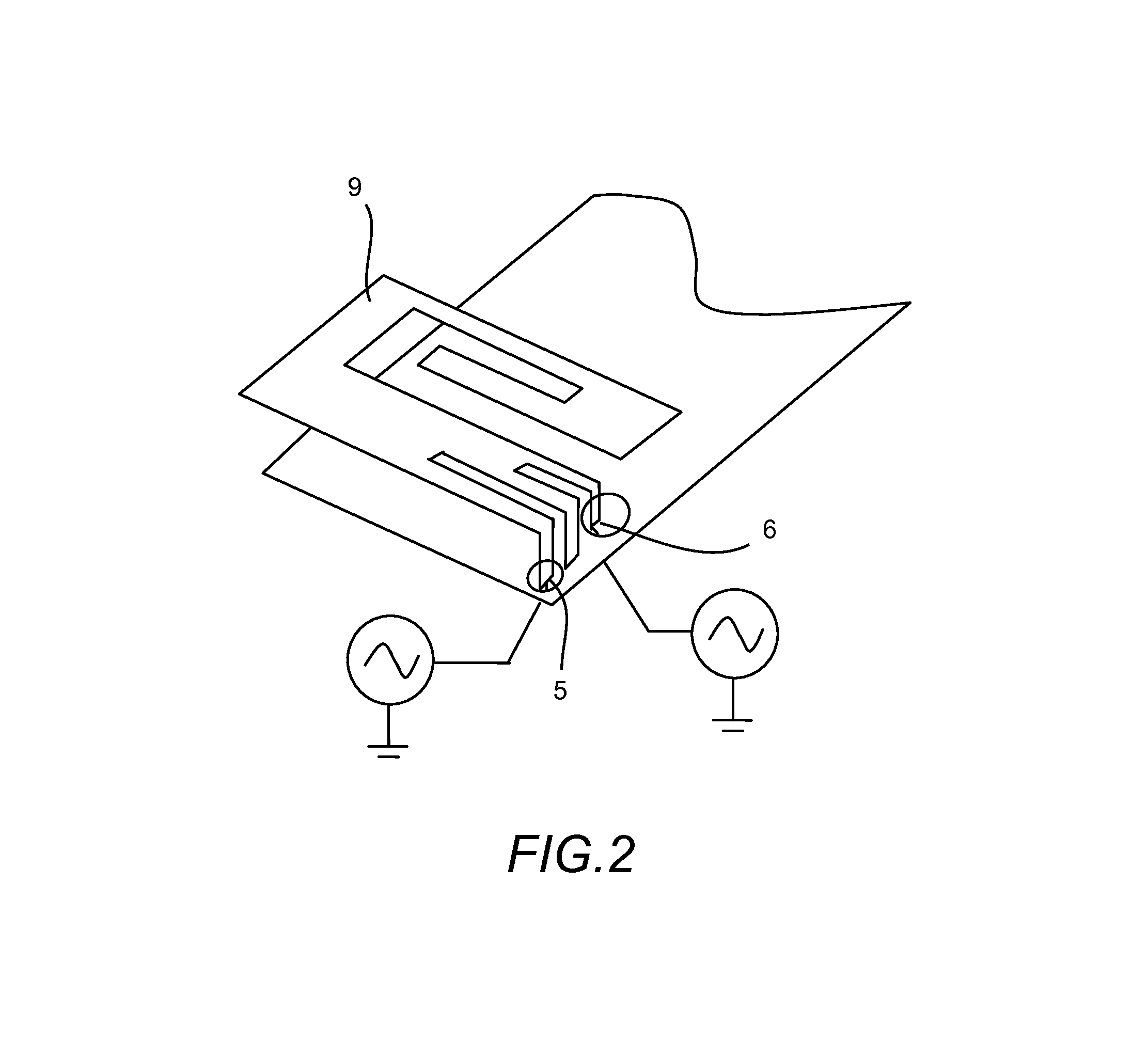
[0040]With reference to FIGS. 1(a-b), the Isolated Magnetic Dipole (IMD) antenna, described in a number of commonly-owned US Patents as referenced above, generally includes a first portion 1, a second portion 2, and a connecting portion 3 therebetween, the first portion 1 and second portion 2 being separated by a gap, wherein the first portion 1, second portion 2, and connecting portion 3 are substantially disposed within a comm...


PUM


Abstract

An antenna comprised of multiple feed ports with independent tuning of the antenna at each feed port to optimize the impedance match between the antenna and transceivers connected to the ports. Filters designed into one or several of the feed ports to provide isolation between the multiple ports and to adjust the frequency response at each port. One or multiple active components connected to the feed ports to provide dynamic tuning of the coupled or driven elements.

Description

CROSS REFERENCE TO RELATED APPLICATIONS[0001]This application is a CIP of U.S. patent application Ser. No. 13 / 289,901, filed Nov. 4, 2011, and titled “Antenna With Active Elements”;[0002]which is a CON of U.S. patent application Ser. No. 12 / 894,052, filed Sep. 29, 2010, and also titled “Antenna With Active Elements”;[0003]which is a CON of U.S. patent application Ser. No. 11 / 841,207, filed Aug. 20, 2007, and also titled “Antenna With Active Elements”;[0004]the entire contents of each of which are hereby incorporated by reference.FIELD OF INVENTION[0005]The present invention relates generally to the field of wireless communication. In particular, the present invention relates to antennas and methods of improving frequency response and selection for use in wireless communications.BACKGROUND OF THE INVENTION[0006]Commonly Owned U.S. Pat. Nos. 7,339,531, awarded Mar. 4, 2008 entitled “Multi Frequency Magnetic Dipole Antenna Structures and Method of Reusing the Volume of an Antenna”; 6,9...

Claims


Application Information

Patent Timeline
IPC IPC(8): H01Q9/16
CPCH01Q5/0068H01Q9/145H01Q5/0058H01Q5/0065H01Q1/243H01Q9/42H01Q9/0442H01Q5/0041H01Q5/0048H01Q5/0072H01Q9/0421H01Q5/0055H01Q5/335H01Q5/35H01Q5/364H01Q5/40
Inventor DESCLOS, LAURENTROWSON, SEBASTIANSHAMBLIN, JEFFREY
Owner KYOCERA AVX COMPONENTS (SAN DIEGO) INC
Why Eureka
Try Eureka