Process for creating facet-specific electronic banding compensation profiles for raster output scanners

a technology of electronic banding compensation and raster output, which is applied in the direction of digital output to print units, instruments, digitally marking record carriers, etc., can solve the problems of periodic density variations in the process direction, inacceptable reprographic printing systems, and variations in the density of marking materials fused to the final print medium

Inactive Publication Date: 2014-02-11
XEROX CORP
View PDF39 Cites 2 Cited by
  • Summary
  • Abstract
  • Description
  • Claims
  • Application Information

AI Technical Summary

Problems solved by technology

Final image quality is affected by various sources of noise and errors in a reprographic system, leading to density variations in the marking material fused to the final print medium.
Certain sources of reprographic system noise and errors caused periodic density variations in the process direction, which are sometimes referred to as “banding” errors.
Other sources of banding errors include gears, pinions, and rollers in charging and development modules; jitter and wobble in imaging modules, as well as photoreceptors and associated drive trains.
If not addressed, such periodic process direction density variations can render a reprographic printing system unacceptable, particularly where the banding errors are visually perceptible.
There are many various errors that produce banding at the 1× (and multiples) of the revolution frequency of the MPA (motor polygon assembly) in reprographic systems using a raster output scanner.
In practice, it is difficult to completely eliminate the error sources that contribute to MPA harmonic banding, or even to reduce them enough to avoid perceptible periodic density variations.
However, conventional banding compensation approaches do not address cross-process (fast scan) direction density variation in banding, and instead average test prints in the cross-process direction to get a one-dimensional banding profile which is then used to derive the banding compensation independent of cross-process banding density variation information.

Method used


Image

  • Process for creating facet-specific electronic banding compensation profiles for raster output scanners
  • Process for creating facet-specific electronic banding compensation profiles for raster output scanners
  • Process for creating facet-specific electronic banding compensation profiles for raster output scanners

Examples


Embodiment Construction

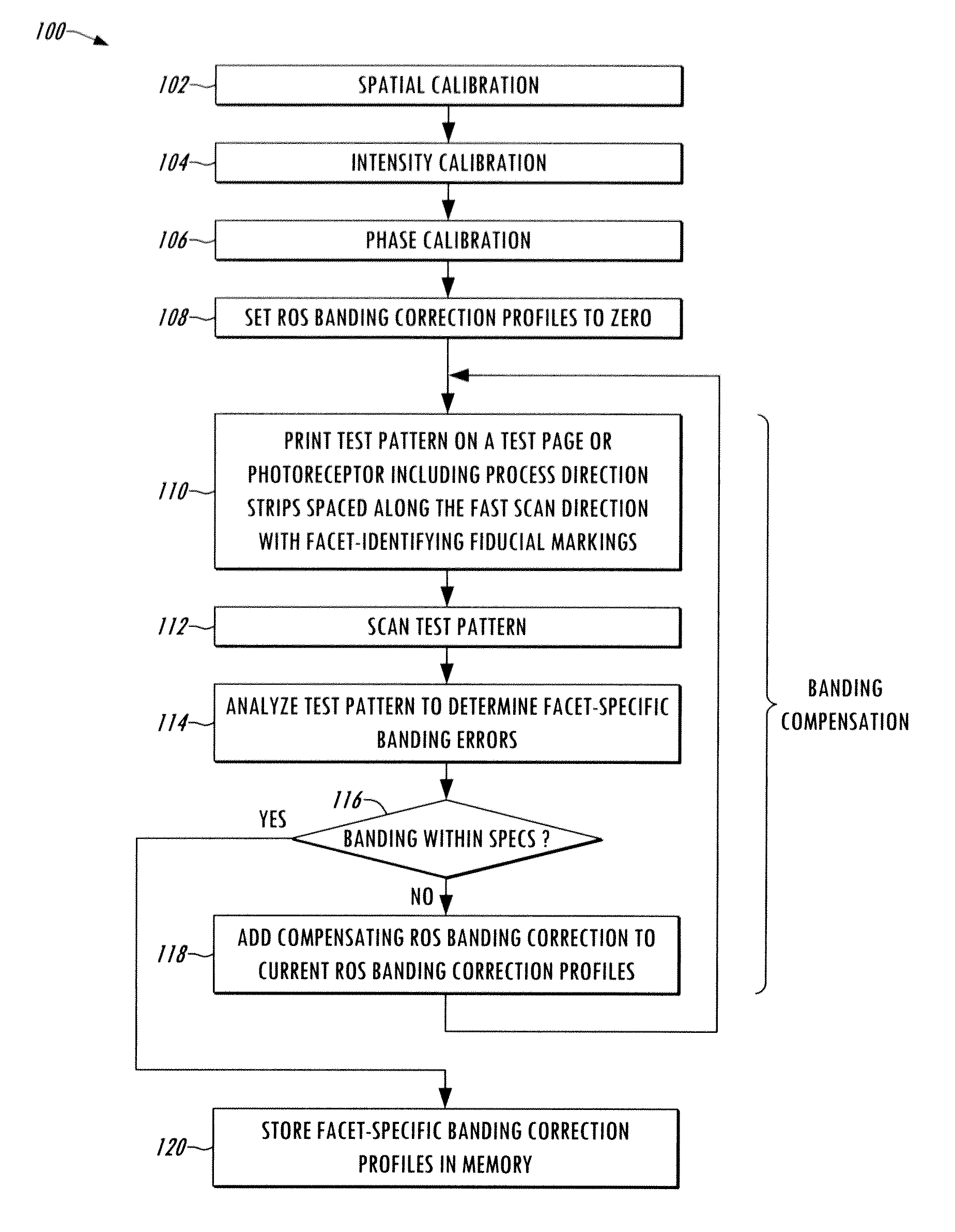
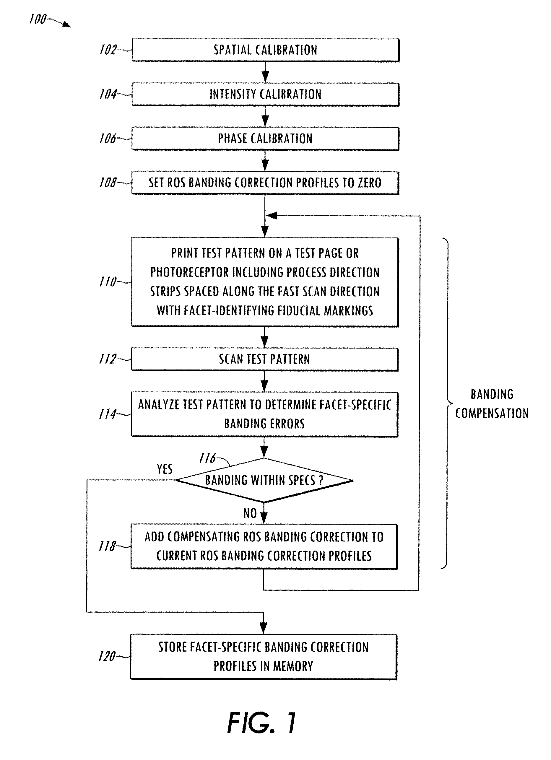
[0027]Several embodiments or implementations of the different aspects of the present disclosure are hereinafter described in conjunction with the drawings, wherein like reference numerals are used to refer to like elements throughout, and wherein the various features, structures, and graphical renderings are not necessarily drawn to scale.

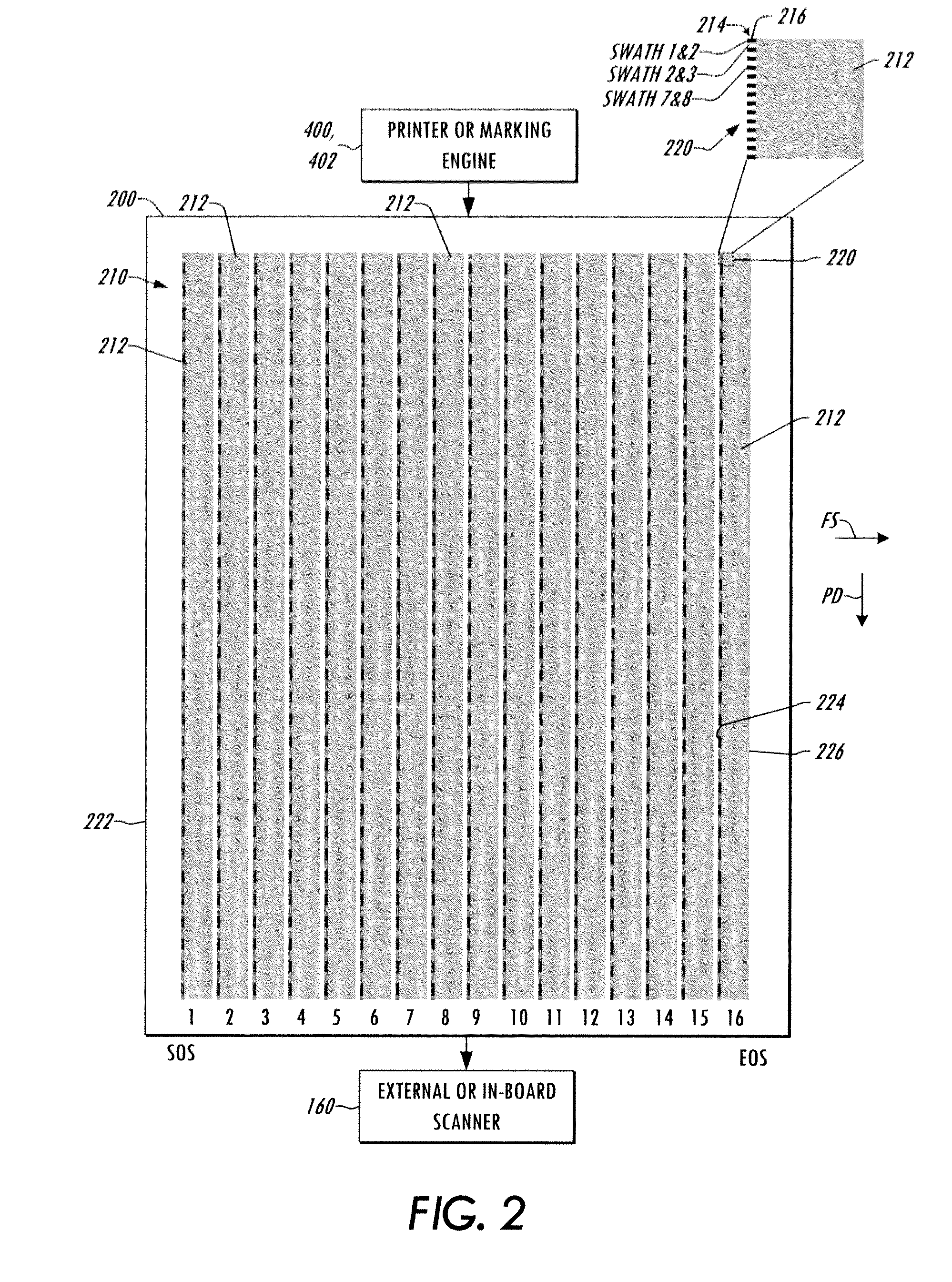
[0028]The disclosure relates to document processing systems generally and to techniques and apparatus for addressing banding errors through use of electronic banding compensation profiles to alter the light intensity output of one or more ROS light sources for electronic banding compensation. U.S. patent application Ser. No. 13 / 313,533, filed Dec. 7, 2011 illustrates and describes ROS apparatus and document processing systems, as well as techniques for performing electronic banding compensation in operation, and the entirety of that application is incorporated herein by reference. The concepts of the present disclosure provide techniques for genera...


PUM


Abstract

Processes are presented for creating electronic banding compensation profiles for raster output scanner (ROS) devices by printing and scanning a test pattern having a series of strips extending along a process direction and spaced from one another along a cross process (fast scan) direction, analyzing the scanned data to determine facet-specific banding errors corresponding to individual strips, and selectively adjusting banding correction profiles to counteract the banding errors.

Description

REFERENCE TO RELATED APPLICATIONS AND INCORPORATION BY REFERENCE[0001]This application is related to U.S. patent application Ser. No. 13 / 313,533, filed Dec. 7, 2011 and entitled “PRINTING SYSTEM, RASTER OUTPUT SCANNER, AND METHOD WITH ELECTRONIC BANDING COMPENSATION USING FACET-DEPENDENT SMILE CORRECTION”, the entirety of which is hereby incorporated by reference as if fully set forth herein. The following documents are incorporated by reference in their entireties: U.S. Pat. App. Publication No. 2011 / 0058186 to Ramesh et al., filed Sep. 8, 2009, Least Squares Based Coherent Multipage Analysis of Printer Banding for Diagnostics and Compensation; U.S. Pat. App. Publication No. 2011 / 0058226 to Ramesh et al., filed Sep. 8, 2009, Banding Profile Estimation using Spline Interpolation; U.S. Pat. App. Publication No. 2011 / 0058184 to Ramesh et al., filed Sep. 8, 2009, Least Squares Based Exposure Modulation for Banding Compensation; U.S. Pat. App. Publication No. 2007 / 0052991 to Goodman et ...

Claims


Application Information

Patent Timeline
Patent Type & Authority Patents(United States)
IPC IPC(8): G06K1/00G06F15/00H04N1/00
CPCG03G15/5062H04N1/04B41J2029/3935B41J2/2132G06K15/00
Inventor HERLOSKI, ROBERTSMITH, JR., EDWARD W.MIZES, HOWARD
Owner XEROX CORP
Why Eureka
Try Eureka