Unlock instant, AI-driven research and patent intelligence for your innovation.
Plug-in circuit breaker assembly including insulative retainers
What is Al technical title?
Al technical title is built by PatSnap Al team. It summarizes the technical point description of the patent document.
a circuit breaker and retainer technology, applied in the direction of coupling device details, coupling device connection, securing/insulating coupling contact members, etc., can solve problems such as circuit breakers
Active Publication Date: 2014-02-11
LABINAL
View PDF51 Cites 14 Cited by
Summary
Abstract
Description
Claims
Application Information
AI Technical Summary
This helps you quickly interpret patents by identifying the three key elements:
Problems solved by technology
Method used
Benefits of technology
Problems solved by technology
If the plug-in circuit breaker panel is desired to be mounted in an overhead configuration with the push-pull operating handle of the circuit breakers being disposed generally downward, then a retention problem of the plug-in circuit breakers may result if the plate member, such as a face plate or cover member, is removed, for example, for maintenance or problem diagnosis or correction.
Method used
Image
Click on the blue label to locate the original text in one second.
Reading with bidirectional positioning of images and text.
Examples
example 1
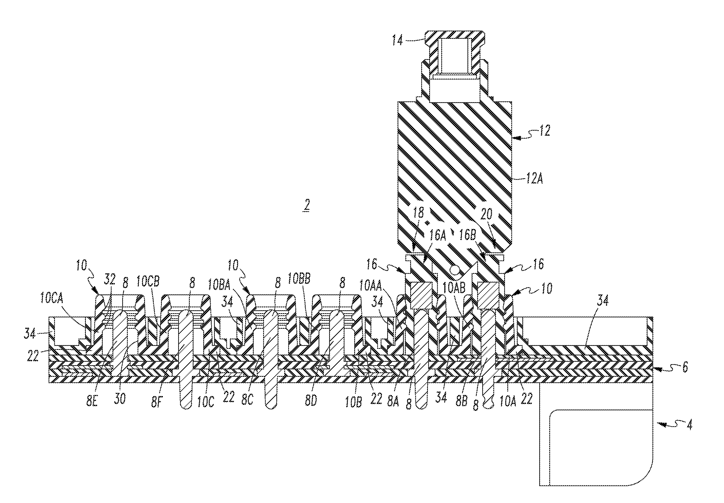
[0036]As shown with the insulative retainers 10B,10C of FIG. 1, the insulative retainers 10 are structured to protect the corresponding pins 8C, 8D, 8E and 8F when they are not electrically engaging the sockets, such as 16A and 16B, of a plug-in circuit breaker, such as 12. As shown, the pins 8C, 8D, 8E and 8F are recessed within the portions 10BA, 10BB, 10CA, 10CB, respectively.
example 2
[0037]Each of the number of first plug-in members is a plurality of male terminals 8A-8B,8C-8D,8E-8F. The number of second plug-in members is a plurality of female sockets 16A-16B. Each of the number of insulative retainers 10A,10B,10C is operatively associated with a plurality of the plurality of male terminals, such as the pins 8A and 8B, and a plurality of the plurality of female sockets, such as the sockets 16A-16B, as shown with the circuit breaker 12 of FIG. 1.
example 3
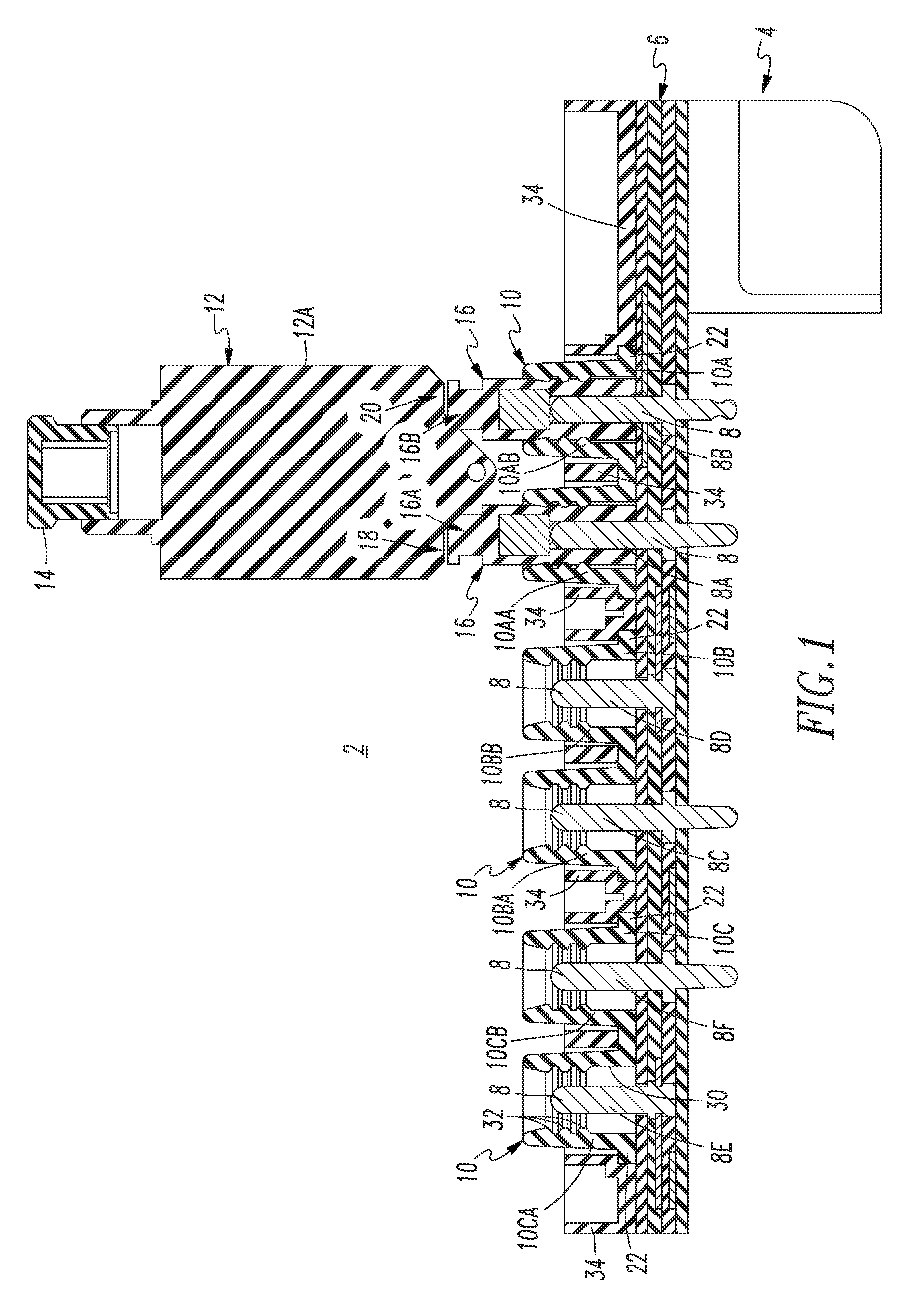
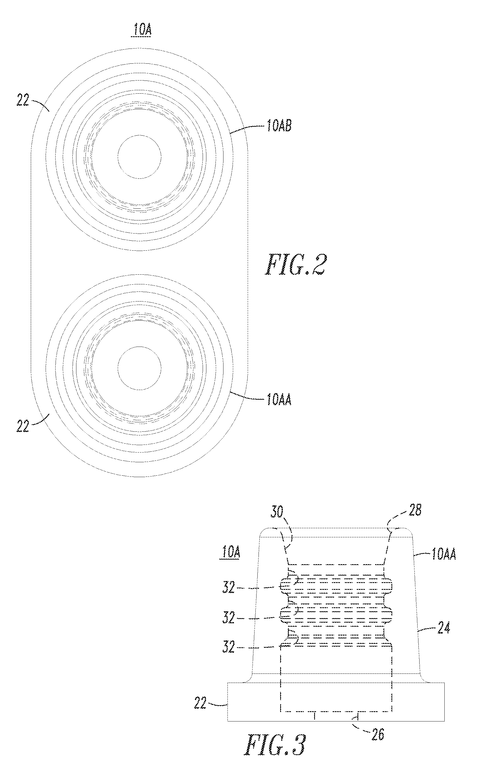
[0038]As best shown with the insulative retainer 10A of FIGS. 2-4, the insulative retainers 10 (FIG. 1) include, for one of the two male terminals 8 and one of the two female sockets 16, an insulator, as shown by the portion 10AA or 10AB, having a base 22 and an elongated portion 24 extending from the base 22. The base 22 has a first aperture 26 therein. The elongated portion 24 has a second aperture 28 therein and a conduit 30 (shown in hidden line drawing in FIG. 3) extending therethrough from the first aperture 26 to the second aperture 28. A pin, such as 8A or 8B, extends through the first aperture 26, into and partially through the conduit 30. A female socket, such as 16A or 16B, extends through the second aperture 28 and partially through the conduit 30. The pin, such as 8A or 8B, electrically engages the female socket, such as 16A or 16B, within the conduit 30.
PUM
Abstract
A circuit breaker assembly includes a housing, an electrical bus structure within the housing, a number of first plug-in members coupled to the bus structure, and a number of insulative retainers coupled to the bus structure. A corresponding one of the number of insulative retainers is operatively associated with a corresponding number of the number of first plug-in members. Each of a number of circuit breakers includes a manual operator and a number of second plug-in members disposed opposite the manual operator. The number of second plug-in members electrically engage a number of the number of first plug-in members. The corresponding one of the number of insulative retainers is disposed about the corresponding number of the number of first plug-in members, in order to insulate the corresponding number of the number of first plug-in members, and to retain the number of second plug-in members.
Description
BACKGROUND[0001]1. Field[0002]The disclosed concept pertains generally to circuit breakers and, more particularly, to circuit breaker assemblies, such as, for example, circuit breaker panels for a number of circuit breakers.[0003]2. Background Information[0004]Circuit breakers are used, for example, in aircraft electrical systems where they not only provide overcurrent protection but also serve as switches for turning equipment on and off Aircraft or subminiature circuit breakers, for instance, are typically relatively small to accommodate the relatively high-density layout of aircraft circuit breaker panels, which make circuit breakers for numerous circuits accessible to a user. Aircraft electrical systems can consist, for example, of hundreds of circuit breakers, each of which is used for a circuit protection function as well as a circuit disconnection function through a push-pull handle.[0005]The circuit breaker push-pull handle is moved from in-to-out in order to open the corres...
Claims
Application Information
Patent Timeline
Application Date:The date an application was filed.
Publication Date:The date a patent or application was officially published.
First Publication Date:The earliest publication date of a patent with the same application number.
Issue Date:Publication date of the patent grant document.
PCT Entry Date:The Entry date of PCT National Phase.
Estimated Expiry Date:The statutory expiry date of a patent right according to the Patent Law, and it is the longest term of protection that the patent right can achieve without the termination of the patent right due to other reasons(Term extension factor has been taken into account ).
Invalid Date:Actual expiry date is based on effective date or publication date of legal transaction data of invalid patent.
Patent Type & Authority Patents(United States)
IPC IPC(8): H02B1/14
CPCH02B1/056H02B1/14H02B1/04H01R13/627H01R13/52
Inventor MILLS, PATRICK W.MCCORMICK, JAMES M.BENSHOFF, RICHARD G.
