Cleaning appliance

a technology for cleaning appliances and cleaning equipment, applied in the field of cleaning appliances, can solve problems such as the use of cleaning objects, and achieve the effect of large area coverag

Inactive Publication Date: 2014-02-18
CARL FREUDENBERG KG
View PDF16 Cites 0 Cited by
  • Summary
  • Abstract
  • Description
  • Claims
  • Application Information

AI Technical Summary

Benefits of technology

[0003]The problem to be solved by the present invention is to provide a cleaning appliance that enables large area coverage even in hard-to-reach spaces.

Problems solved by technology

Although this cleaning appliance provides large area coverage due to its flat cleaning surface, it can only be used to clean objects the dimensions of which are smaller than the width of the recess.

Method used


Image

  • Cleaning appliance
  • Cleaning appliance
  • Cleaning appliance

Examples


Embodiment Construction

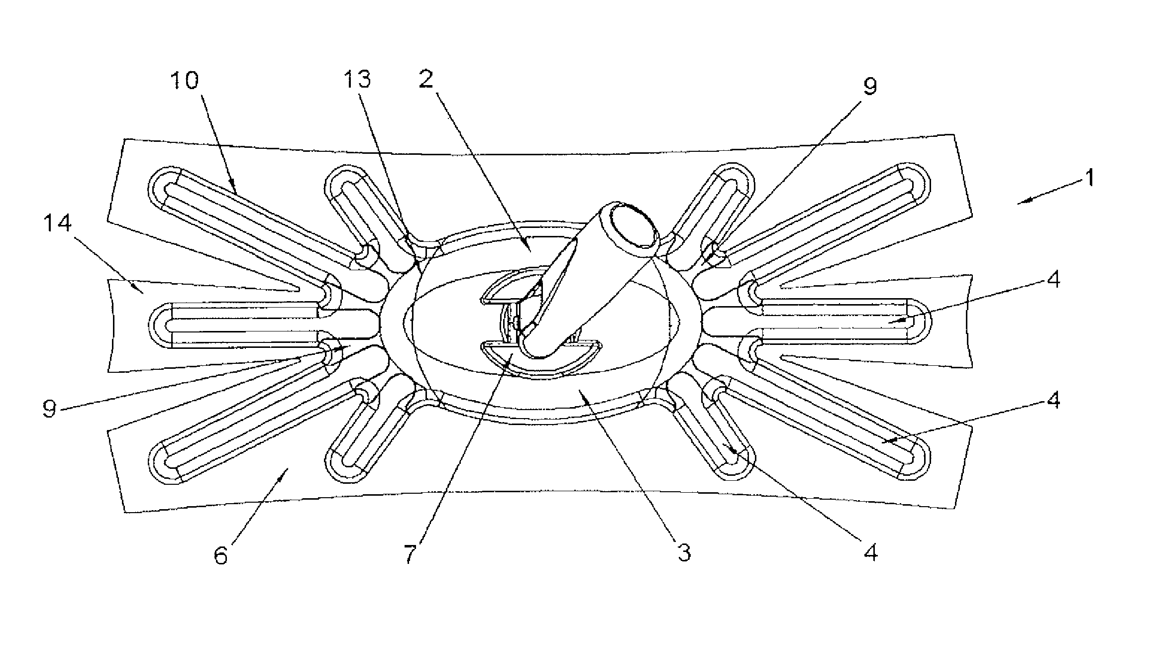
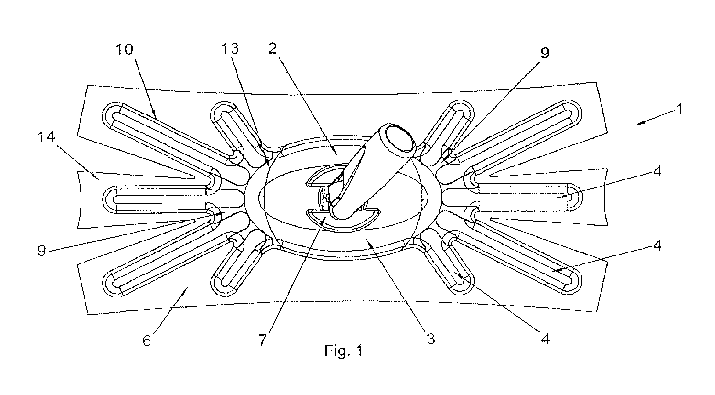
[0029]FIG. 1 illustrates a cleaning appliance 1 designed as a dust wiping appliance for cleaning dry surfaces. The cleaning appliance 1 includes a wiper plate 2 having a central region 3 from both ends of which five arms 4 each extend in a ray-shaped configuration. A cleaning cloth 6 is detachably secured by an anchoring mechanism 10 in the form of a hook and loop fastener to the cleaning surface 5 of the wiper plate 2, i.e., the lower surface. In the section associated with the central region 3, the cleaning cloth 6 lies flat, and in the sections associated with the arms 4 it lies in a linear configuration, on the floor to be cleaned. A handle attachment mechanism 7 is integrated into the central region 3. The arms 4 are attached to the central region 3 in a star-like configuration and are designed and disposed in such a manner that the wiper plate 2 has a rectangular boundary edge. The aims 4 are spring-mounted on the central region 3 via joining strips 8, with the arms 4, the joi...


PUM

PropertyMeasurementUnit
circumferenceaaaaaaaaaa
thermoplasticaaaaaaaaaa
widthaaaaaaaaaa

Abstract

The invention relates to a cleaning appliance (1) including a wiper plate (2) having a central region (3) from which a plurality of arms (4) extend on both sides. The wiper plate (2) includes a cleaning side (5) to which a cleaning cloth (6) can be fixed. The cleaning cloth is placed on the floor to be cleaned, with a flat surface in the section associated with the central region (3), and essentially linearly in the sections associated with the arms (4).

Description

TECHNICAL FIELD[0001]The present invention relates to a cleaning appliance with a wiper plate having a central region.BACKGROUND OF THE INVENTION[0002]Cleaning appliances designed for cleaning hard-to-reach spaces are known from the prior art. In particular, it is useful to design dusting cleaning appliances to also dust hard-to-reach spaces since dust tends to accumulate in such areas. The cleaning appliance disclosed in EP 1 097 667 B1 is especially well suited to clean floors in the vicinity of heating pipes. To this end, this cleaning appliance has recesses along the short sides of the wiper plate, which, when cleaning, can engage with heating pipes, thus making it possible to clean the floor in the vicinity of the heating pipes. Although this cleaning appliance provides large area coverage due to its flat cleaning surface, it can only be used to clean objects the dimensions of which are smaller than the width of the recess.BRIEF SUMMARY OF THE INVENTION[0003]The problem to be s...

Claims


Application Information

Patent Timeline
Patent Type & Authority Patents(United States)
IPC IPC(8): A47L13/24A47L13/44
CPCA47L13/256A47L13/20
Inventor DINGERT, UWECLEMEN, HANS JORG
Owner CARL FREUDENBERG KG
Why Eureka
Try Eureka