System for Dynamically Controlling the Gain of a Repeater

a repeater and gain control technology, applied in the field of dynamic control of repeater gain, can solve the problems of reducing information bit energy (eb), poor coverage, reducing signal power, etc., and achieves the effects of reducing signal power, poor coverage, and large area coverag

Active Publication Date: 2016-10-06
NEXTIVITY INC
View PDF4 Cites 2 Cited by
  • Summary
  • Abstract
  • Description
  • Claims
  • Application Information

AI Technical Summary

Benefits of technology

[0004]One main reason for the impaired indoor coverage is that cellular base stations are usually placed outside buildings, at positions that are typically higher than the average building heights, to provide large area coverage. Although the signal may be adequate at street-level, it is severely attenuated by a building's material as it passes through such buildings, reducing the signal power in-building, resulting in poor coverage. Loss of signal power (attenuation) depends on the building material and can be tens of decibels (dBs) for each wall penetration. The problem is exacerbated in third generation systems such as Wideband Code Division Multiple Access (WCDMA) and cdma2000, as these new systems have the capability of high data transmission, which results in lower information bit energy (Eb), and much reduced link budget and cellular footprint.
[0005]Typical solutions for providing indoor coverage are expensive and involve extensive investment in the cellular network infrastructure and are much more complex in planning and operation. One solution involves the use of a cellular repeater. Typically, repeaters operate in a manner that does not harm and / or effect the operations of the wireless communications network in which it operates. One of the fundamental tasks performed by a repeater for operating in such a manner is controlling the gain of the repeater. The repeater controls its gain to avoid increasing the interference levels in the wireless communications network. Typical repeater systems react to events in the wireless communications network much slower than the occurrence of those events, such as, for example, the start of a signal transmission in the uplink.

Problems solved by technology

However, despite careful network design, indoor (in-building) coverage, or the coverage of places with high shadowing attenuation (e.g. tunnels) of such networks is often “patchy”, with coverage “holes” at best, and no coverage at worst.
Although the signal may be adequate at street-level, it is severely attenuated by a building's material as it passes through such buildings, reducing the signal power in-building, resulting in poor coverage.
The problem is exacerbated in third generation systems such as Wideband Code Division Multiple Access (WCDMA) and cdma2000, as these new systems have the capability of high data transmission, which results in lower information bit energy (Eb), and much reduced link budget and cellular footprint.
Typical solutions for providing indoor coverage are expensive and involve extensive investment in the cellular network infrastructure and are much more complex in planning and operation.
The system may freeze the input gain of a repeater when no input signal is present.

Method used


Image

  • System for Dynamically Controlling the Gain of a Repeater
  • System for Dynamically Controlling the Gain of a Repeater
  • System for Dynamically Controlling the Gain of a Repeater

Examples


Embodiment Construction

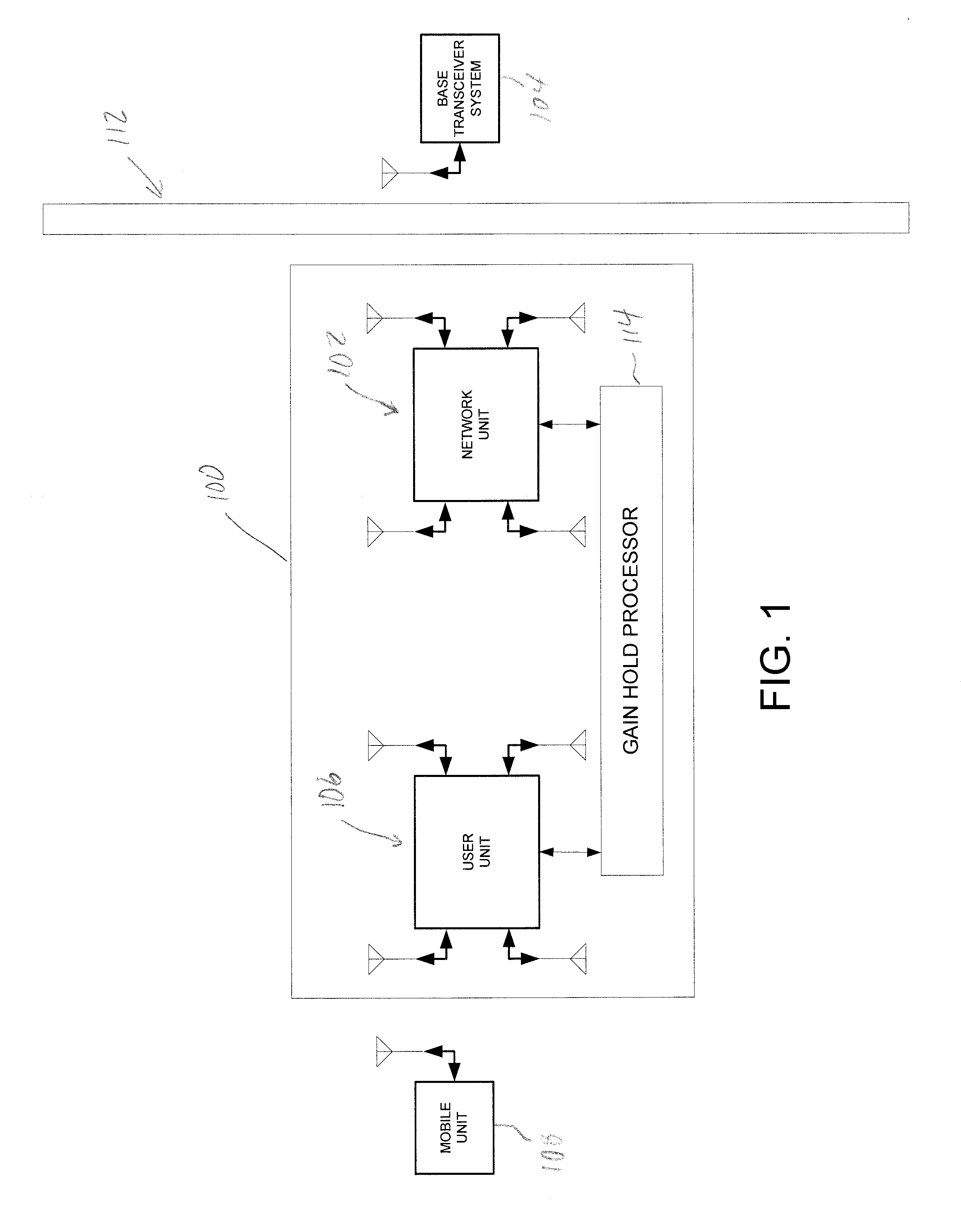
[0015]FIG. 1 illustrates a cellular repeater 100 having a network 102 having a donor antenna adapted to communicate with one or more base transceiver systems 104 (or “base station”), and a user unit 106 having a server antenna adapted to communicate with a mobile unit 108. Examples of the mobile unit 108 include wireless communication devices such as a cellular phone, laptop computer, desktop computer, tablet computer, or personal digital assistant (PDA). Thus, the cellular repeater 100 is suited for an environment such as a home or building 112, to receive signals from the selected base station 104, boost, or add gain to, the signals, and send the boosted signals to the mobile unit 108, and back again from the mobile unit 108 to the selected base station 104.

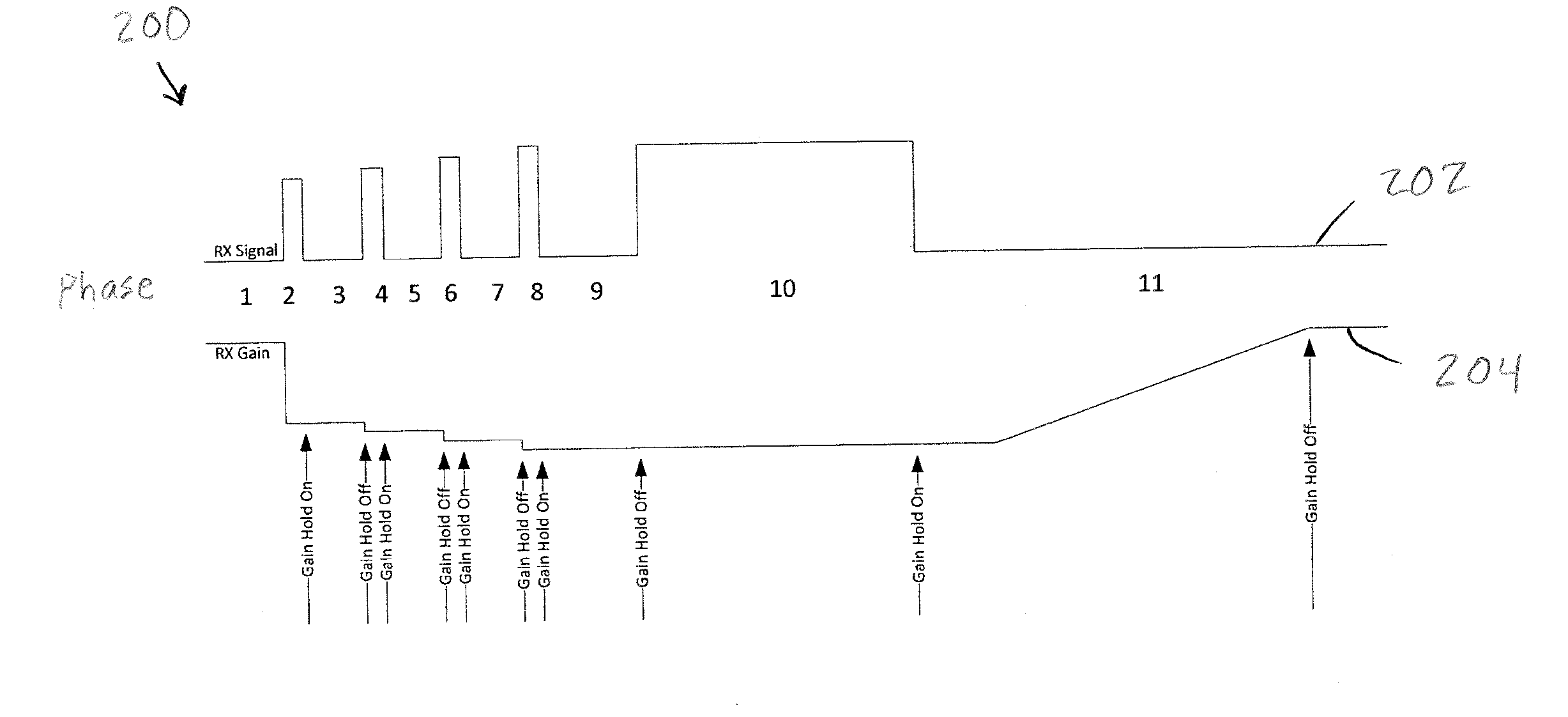
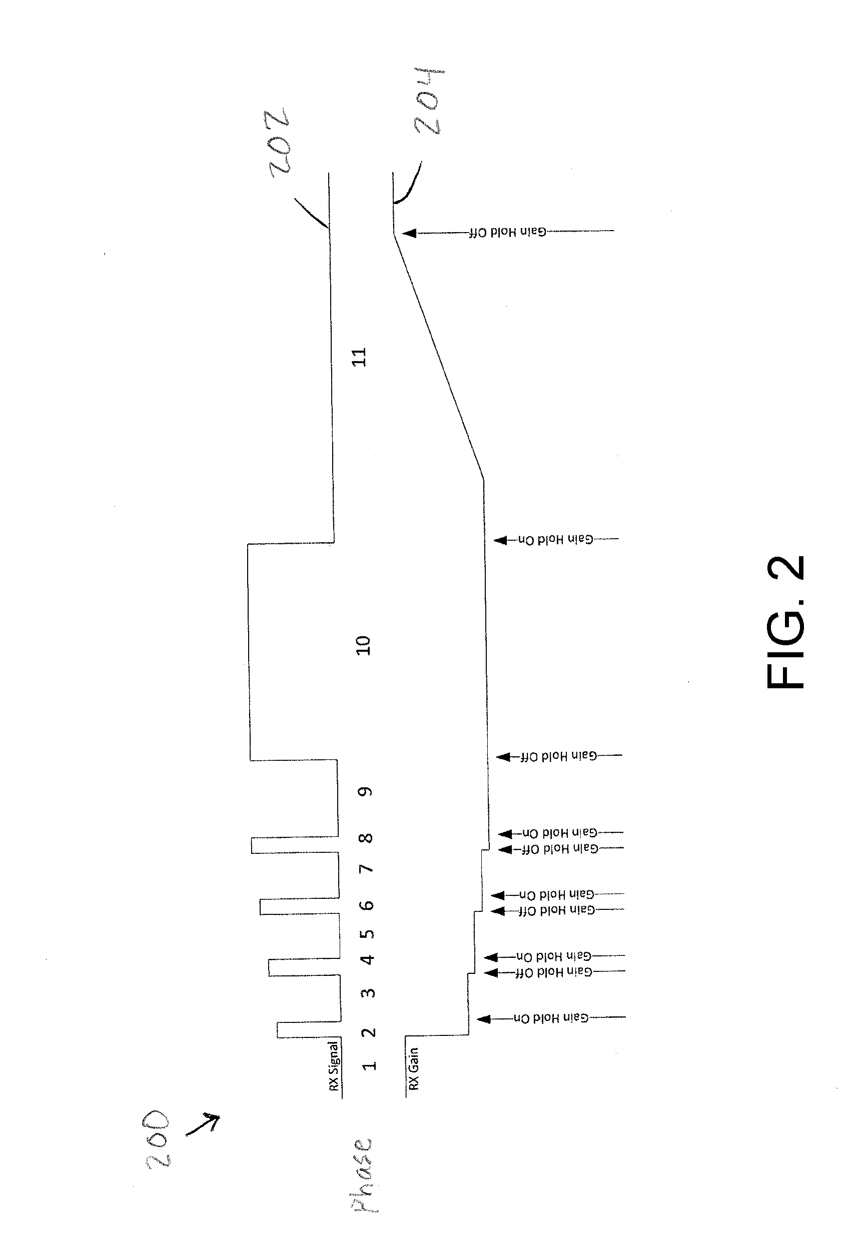
[0016]The cellular repeater further includes a gain hold processor 114 that is configured for preempting large up-steps in signal power levels that follow large down-steps in signal power levels of signals received by the cellu...


PUM


Abstract

A repeater configured to dynamically affect the gain level of the repeater in response to the input signal power level over time. The repeater system includes a gain hold processor executing a gain hold algorithm. The gain hold algorithm preempts a large up-step in signal power level to follow a large down-step in signal power level. After a large up-step in input signal is detected, the system holds the gain level in response to a drop in input signal level after the large up-step. The gain is held at the level set by the large burst of input signal power to the repeater. In response to a larger up-step in signal power level, the system will lower the gain. In response to a large down-step in signal power after the larger up-step in signal power level, the system will hold the gain level of the repeater. During a prolonged low-power level or zero power signal at the input of the repeater, the system will slowly raise the gain level of the repeater over time.

Description

CROSS-REFERENCE TO RELATED APPLICATION[0001]This application claims priority to and the benefit of U.S. Provisional Patent Application No. 62 / 143,736, filed on Apr. 6, 2015 and titled “SYSTEM FOR DYNAMICALLY CONTROLLING THE GAIN OF A REPEATER,” the disclosure of which is incorporated by reference in its entirety.TECHNICAL FIELD[0002]The subject matter described herein relates generally to the field of wireless communication and data networks. More particularly, in one exemplary embodiment, the disclosure is directed to dynamically controlling the gain of a repeater.BACKGROUND AND SUMMARY[0003]Existing cellular networks, such as (Global System for Mobile Communications (GSM) and IS95, are intended to provide contiguous and continuous coverage for cellular communication terminals, so as to support a high terminal mobility expected from such systems. However, despite careful network design, indoor (in-building) coverage, or the coverage of places with high shadowing attenuation (e.g. t...

Claims


Application Information

Patent Timeline
Patent Type & Authority Applications(United States)
IPC IPC(8): H04B7/155
CPCH04B7/15535H04W16/26H04W84/047Y02D30/70Y02B70/30
Inventor RIPHAGEN, IAN
Owner NEXTIVITY INC
Why Eureka
Try Eureka