Reading data in probe-based storage devices

a data storage device and data technology, applied in the field of methods and apparatuses, can solve problems such as the limit of achievable data rate, and achieve the effect of higher data ra

Inactive Publication Date: 2006-09-05
IBM CORP
View PDF3 Cites 1 Cited by
  • Summary
  • Abstract
  • Description
  • Claims
  • Application Information

AI Technical Summary

Benefits of technology

[0013]In a preferred embodiment of the present invention, there is provided a method for reading back information written in a probe storage device based on an AFM cantilever array, in which each cantilever circuit is electrically equivalent to an RLC circuit comprising a resistance R, an inductance L, and a capacitance C. Rather than relying on variation of a cantilever resistance in dependence on temperature at the tip of a heated cantilever, sensing whether a “1” or a “0” is recorded is achieved by applying to the “cold” cantilever a sinusoidal wave form having a frequency equal to the resonant frequency of the RLC circuit, and observing the wave form at the output of the RLC circuit to detect a variation in the circuit transfer characteristics. For example, a variation of the phase characteristic can be obtained from variation of one or both reactance values of the RLC circuit (L and / or C). Such a variation is induced by movement of the probe over a “pit” or a “no pit”. Many advantages over conventional thermo-mechanical reading techniques are achieved by this technique. As the read back process does not involve heating the cantilever to a relatively high temperature of about 350 degrees C., the rate at which reading can be performed is not limited by a thermal time constant. Thus, higher data rates can be achieved. Furthermore, a lower signal power is involved in detection because no signal energy is converted into thermal energy for heating the cantilever. Additionally, because the identity of a bit as a “1” or a “0” is encoded as a variation of phase and / or amplitude of a sinusoidal signal, detection of the useful signal does not take place in the presence of a large offset signal, as occurs in the case of thermo-mechanical reading.

Problems solved by technology

As a consequence, an important issue in detecting the presence or absence of a pit is a sufficiently high resolution to permit extraction of the signal that contains the information about the bit being “1” or “0”.
Another problem encountered with time-multiplexed read operations based on thermo-mechanical sensing stems from an inherent limitation to achievable data rate which is determined by the cantilever thermal time constant.

Method used


Image

  • Reading data in probe-based storage devices
  • Reading data in probe-based storage devices
  • Reading data in probe-based storage devices

Examples


Embodiment Construction

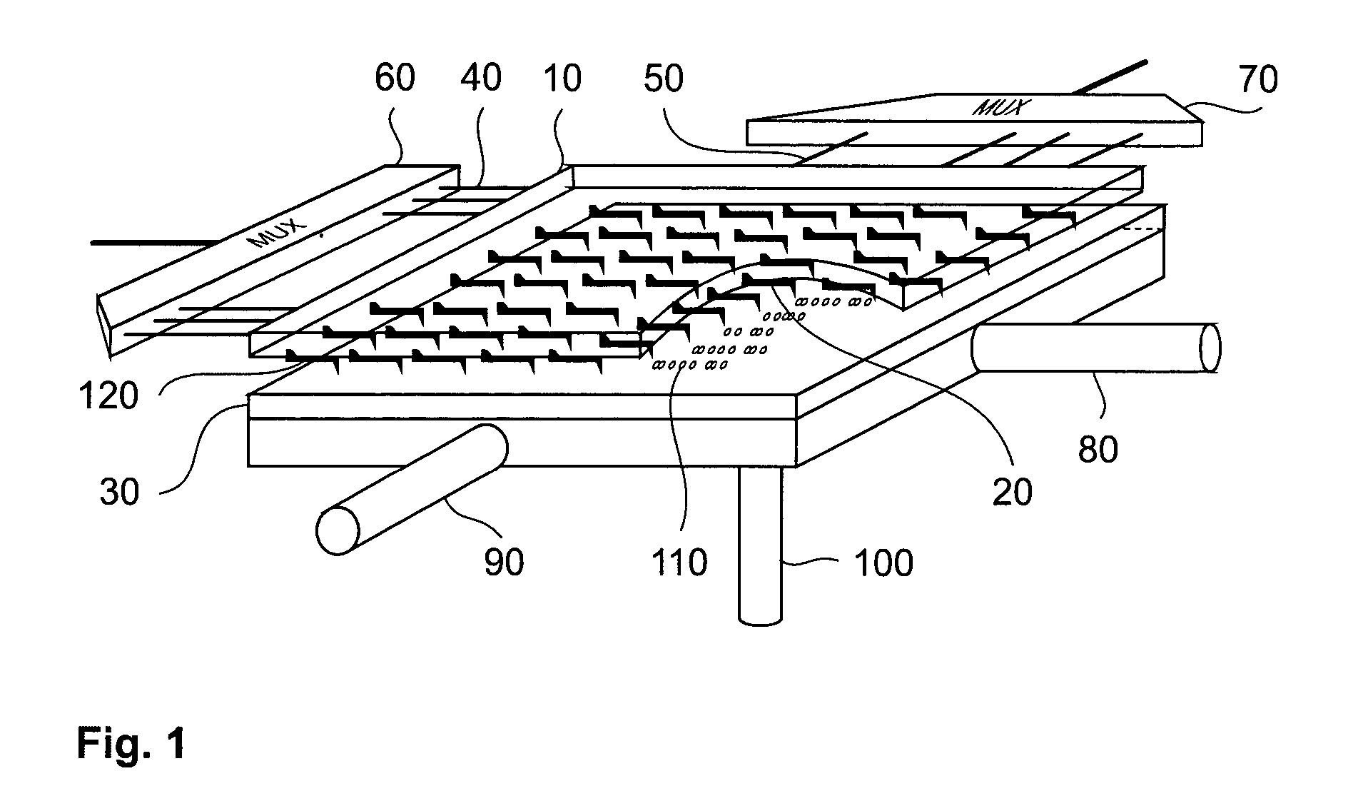
[0023]Referring first to FIG. 1 an example of a probe storage device embodying the present invention comprises a substrate 10 having a two dimensional array 120 of probe cantilever sensors 20 facing a storage surface 30. The cantilevers 20 are connected to row conductors 40 and column conductors 50. Each cantilever 20 is addressed by a different combination of a row conductor 40 and a column conductor 50. The row conductors 40 are selectively addressed via a row multiplexer 60. Similarly, the column conductors 50 are selectively addressed via a column multiplexer 70. The storage surface 30 is mounted on a scanner mechanism comprising an x position transducer 80, a y position transducer 90 and a z position transducer 100. In operation, the z transducer 100 moves the storage surface 30 towards or away from the array 120. The x transducer 80 and the y transducer 90 move the storage surface 30 in orthogonal directions relative to and within a plane parallel to the array 120. The transdu...


PUM

PropertyMeasurementUnit
temperatureaaaaaaaaaa
inductanceaaaaaaaaaa
diameteraaaaaaaaaa

Abstract

A probe-based storage device comprises a storage surface for storing data represented by deformations in the surface. A probe faces the surface and includes a resonant circuit having a reactance dependent on deflection of the probe relative to the surface. A scanner is provided for scanning the probe across the surface such that the probe follows said deformations. A detector reads data stored on the surface by detecting variation of the resonant frequency of said circuit.

Description

BACKGROUND OF THE INVENTION[0001]1. Technical Field[0002]The present invention relates to a method and apparatus for reading data in probe-based data storage devices.[0003]2. Discussion of Related Art[0004]Techniques employing nanometer-sharp tips for imaging and investigating the structure of materials down to the atomic scale, such as the atomic force microscope (AFM) and the scanning tunneling microscope (STM), also find application in ultra high density storage devices. See, for example, U.S. Pat. No. 4,575,822 and P. Vettiger et al., “The Millipede—More than one thousand tips for future AFM data storage,” IBM Journal of Research and Development, vol. 44 No. 3 May 2000, pp. 323–340. In the device described by Vettiger, information is stored as sequences of “pits” and “no pits” written on a polymer storage surface via an array of cantilevers each carrying a tip. The cantilevers, and the tips thereon, are selectively heated to write data onto the surface. The heating of each tip t...

Claims


Application Information

Patent Timeline
Patent Type & Authority Patents(United States)
IPC IPC(8): G11B9/00G01Q60/46G01Q80/00G06F12/08G11B9/06G11B9/14G11B11/16G11B11/26
CPCB82Y10/00G11B9/14G11B2005/0021G11B9/1418G11B11/16G11B9/1409G06F12/08
Inventor GIOVANNI, CHERUBINI
Owner IBM CORP
Why Eureka
Try Eureka