
Device for connecting two pipes with different external diameters

a technology of external diameter and pipe, which is applied in the direction of pipe connection arrangement, pipe/joint/fitting, sleeves/socket joints, etc., can solve the problems of unfavorable spatial deformation process, adverse effect of connection seal, and inability to achieve a targeted spatial deformation process, etc., to achieve low cost production, easy sealing, and high quantity

Active Publication Date: 2014-02-18
FELBER WINFRIED
View PDF17 Cites 11 Cited by
  • Summary
  • Abstract
  • Description
  • Claims
  • Application Information

AI Technical Summary

Benefits of technology

The invention proposes a new design for a fixing sleeve that can be adjusted to different diameters to prevent leaks and facilitate the alignment of pipes. The clips assigned to the contact sections of the fixing sleeve consist of at least two segments that produce an arc angle of more than 360°. This design ensures a uniform radial movement over the entire circumference, which benefits the precise alignment of the pipes. The invention eliminates the need for compensating rings and simplifies production, making it suitable for various applications.

Problems solved by technology

However, this has proved to be both complicated and uneconomical since different compensating rings have had to be kept at the ready for different diameter differences.
The compensating rings are located in a radial position inside the sealing sleeve and can therefore also have an adverse effect on the seal of the connection.
Although the overlapping ends can move towards each other, it is not possible to achieve a targeted spatial deformation process to adjust to the different external diameters of the pipes that are to be connected due to a lack of suitable three-dimensional deformation capacity, particularly in the central section of the fixing sleeve.
The conventional arrangements are therefore not suitable for connecting two pipes with different external diameters.

Method used


Image

  • Device for connecting two pipes with different external diameters
  • Device for connecting two pipes with different external diameters
  • Device for connecting two pipes with different external diameters

Examples


Embodiment Construction

[0034]The main area of application of the invention is the waste water and sanitary field since it is often necessary in this field to connect pipes made of different materials to each other and therefore, whilst they may have the same internal diameter, they have different external diameters. However, the invention is not restricted to this field.

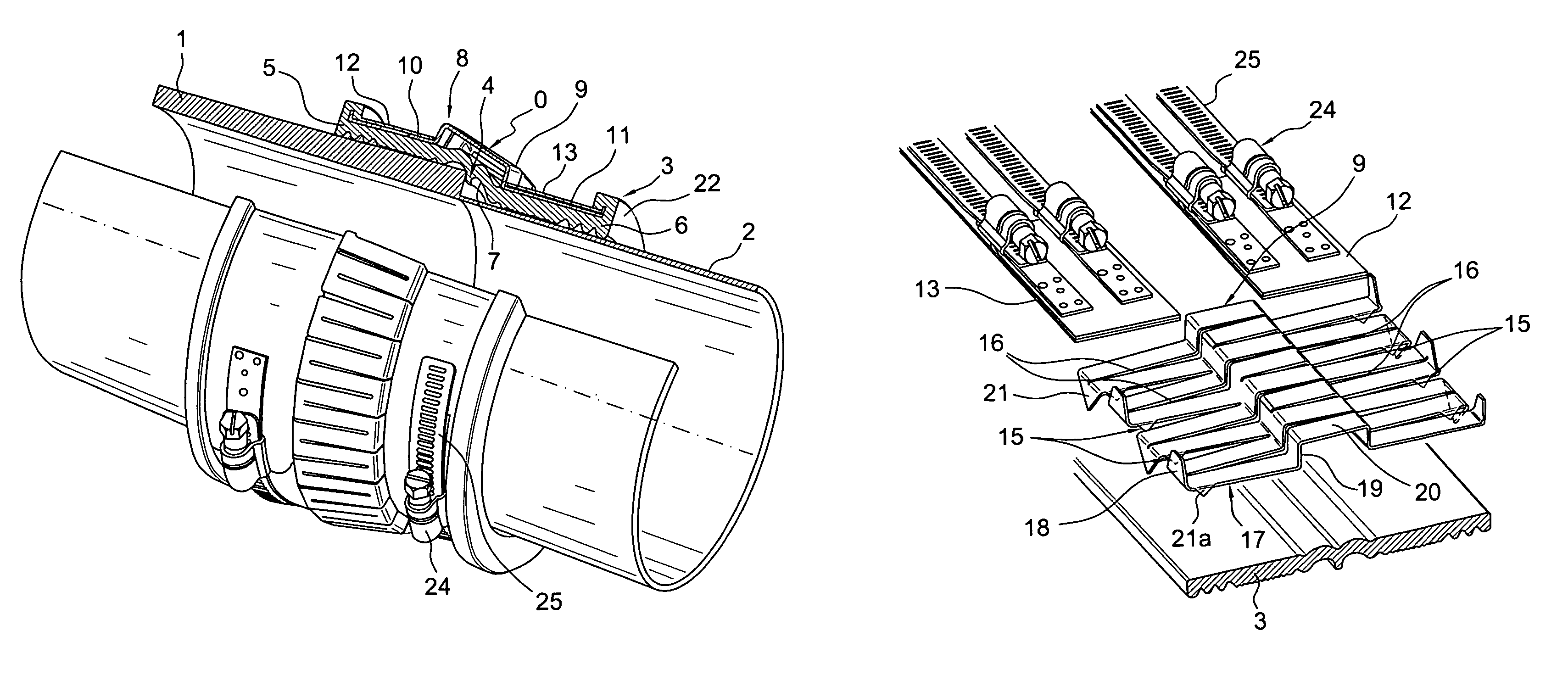
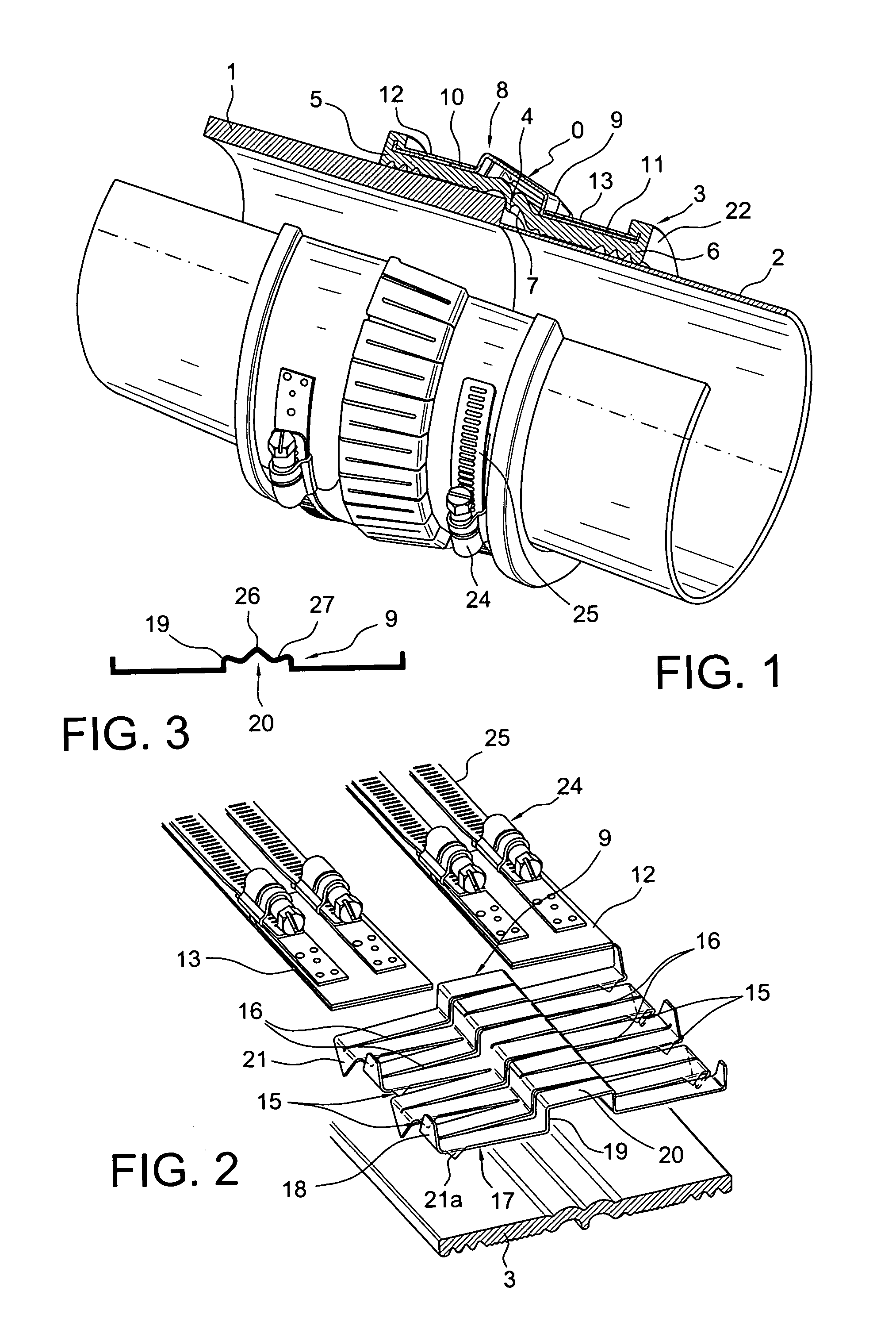
[0035]The example shown in FIG. 1 is based on a connection between a stoneware pipe 1 and a plastic pipe 2 which has a much smaller wall thickness. The pipes 1, 2 have the same internal diameter and are placed against each other coaxially. As a result of their different wall thicknesses, the area around the butt joint forms an external step around the circumference.

[0036]The pipes 1, 2 in the example shown are joined with a butt connection to make the drawing clearer. In practice, however, a small expansion gap must be provided. To ensure the requisite seal around the joint, in the example shown there is a sealing sleeve 3 made of rubber o...


PUM


Abstract

A device for connecting two pipes with different external diameters using a sleeve arrangement which bridges the butt joint between the ends of the pipe facing each other. The device contains at least a fixing sleeve which can take up the clips for the two pipes, and, if necessary, a sealing sleeve which is surrounded by the fixing sleeve. High economy and safety can be achieved by the fact that each sleeve of the sleeve arrangement has cylindrical contact sections which can be adjusted to the different external diameters of the two pipes and are connected by a central section which can take a conical form to suite the diameter difference wherein the contact sections of the sleeve next to the external circumference of the two pipes can be brought into direct contact with the two pipes, and the contact sections of the fixing sleeve contain encircling mounting channels assigned to the clips, and wherein the fixing sleeve takes the form of a closed encircling ring which is suitable for three-dimensional deformation.

Description

FIELD OF THE INVENTION[0001]The invention relates to a device for connecting two pipes with different external diameters with a sleeve arrangement which bridges the butt joint between the ends of the pipe facing each other and contains at least a fixing sleeve which can take up encircling clips assigned to the two pipes and if necessary a sealing sleeve which is surrounded by the fixing sleeve.BACKGROUND OF THE INVENTION[0002]The need to connect lines, in particular pipes with different external diameters, comes about if pipes are found with different wall thicknesses, for example made of different materials, a situation which often occurs in the waste water and sanitary field. In arrangements of the type mentioned above used in the past have used compensating rings which have compensated for the diameter difference between the two pipes. However, this has proved to be both complicated and uneconomical since different compensating rings have had to be kept at the ready for different...

Claims


Application Information

Patent Timeline
Patent Type & Authority Patents(United States)
IPC IPC(8): F16L21/00
CPCF16L21/022F16L49/02F16L21/005F16L25/0072F16L25/14
Inventor FELBER, WINFRIED
Owner FELBER WINFRIED
Learn More