Arteriovenous shunt with integrated surveillance system

a shunt and integrated technology, applied in the field of hemodialysis devices and methods, can solve the problems of significant risk of infection and aneurysm, using conventional av shunts, and weakening of vessel walls, so as to increase the rate at which blood is permitted, increase the rate of blood flow, and reduce the effect of blood flow

Active Publication Date: 2014-02-18
INDIANA UNIV RES & TECH CORP
View PDF13 Cites 39 Cited by
  • Summary
  • Abstract
  • Description
  • Claims
  • Application Information

AI Technical Summary

Benefits of technology

[0011]In another embodiment, shuttle valves may be employed at the anastomosis of the shunt with the blood vessels. Each shuttle valve comprises a valve housing, a skirt for surgically attaching the valve housing to an opening over a blood vessel, an orifice on the side of the valve housing facing the opening in the blood vessel, a shunt connector for attaching and fluidly coupling an AV shunt to the valve housing opposite the blood vessel, and a stopper, movably disposed in the valve housing such that, responsive to operation of a valve control system, the stopper “shuttles” back and forth inside the valve housing in order to alternatively block and unblock the orifice, thereby closing and opening shuttle valve). One end of the stopper in the shuttle valve has an aperture that, when the stopper is moved into the open position, the aperture in the stopper is aligned with the orifice in the valve housing to allow fluid in the blood vessel to pass out of the blood vessel and then into and through the orifice, the aperture, the valve housing, the shunt connector and AV shunt. The other end of the stopper comprises an apron that, when the valve is in the closed position, blocks or obstructs the orifice in the valve housing so as to prevent fluid in the blood vessel from passing through orifice.
[0013]Embodiments of the present invention include an integrated surveillance system configured to collect data representing quantitative measurements characterizing the flow of blood through the vessels at the arterial and venous anastomotic valves. More specifically, the arterial and venous anastomotic valves are equipped with one or more flow sensors that are electrically coupled to a microprocessor in the medial flow control unit via insulated electrical leads. In some embodiments, the insulated electrical leads may be embedded in flexible fluid tubes, interposed between the two anastomotic valves and the medial flow control unit, which carry hydraulic fluid used to provide the mechanical force required to open and / or close the valves. In other embodiments, the insulated electrical leads are independent from the flexible fluid (hydraulic) tubes. In any case, the electrical leads provide electrical connectivity between the flow sensors and the medial flow control unit, which enables transmission of electrical signals representing the values generated from the quantitative measurements, such as pressure, volume and speed values for the blood flowing through the vessels at or near the anastomotic valves.
[0016]In yet another aspect of the invention there is provided a hemodialytic angioacess device for implantation in dialysis patients, comprising an AV shunt, anastomotic valves that connect the AV shunt to blood vessels, a valve control system and an integrated surveillance system that measures flow conditions in the blood vessels in the vicinity of the AV shunt. In some embodiments, data describing the flow conditions through the blood vessels may be collected and stored while the anastomotic valves are closed and the patient is not undergoing dialysis treatment. In other embodiments, the data may be collected and stored while the anastomotic valves are open. In still other embodiments, the data may be collected and stored while the anastomotic valves are open, as well as while the anastomotic valves are closed. The flow condition data, which may include data representing the velocity, pressure and volume of blood flowing through the vessels, is stored in a memory storage area in the device, and transmitted to a health care provider or technician on demand in response to a wired or wireless signal transmitted to the implanted hemodialytic angioaccess device from an external transmitter. Once extracted and transmitted, the data can be used, for example, to calculate compliance and resistance characteristics for the blood vessels, and help detect and identify dangerous conditions, such as turbulence and stasis, which contribute to AV shunt failure, vessel injury and other serious complications for the patient.

Problems solved by technology

Over time, repeated insertion and removal of needles into the patient's arteries and veins weaken the vessel walls and produce a significant risk of developing infections and aneurysms (large bulges in the vessel walls).
Unfortunately, there are a number of problems associated with using conventional AV shunts.
It has been observed, for example, that implantable AV shunts often fail.
Pathological study of the proximal veins of failed AV shunts has revealed a large incidence of myointimal hyperplasia secondary to vessel injury from turbulence, compliance mismatch between shunt material and vein, and mechanical stimulation of perivascular tissues at the anastomosis graft and vessel.
When complications associated with implanted AV shunts, such as myointimal hyperplasia, thrombosis, shunt stenosis and clotting, arise and go undetected for a significant period of time, the AV shunt can fail without warning, resulting in potentially devastating consequences.
The complications also might be detected while the patient is hooked up to complicated and expensive external medical machines and equipment that are designed to monitor and / or test the patient for signs of complications.
Consequently, the frequency and unpredictable timing of AV shunt failures and the emergency salvage procedures required to restore their patency (e.g., thrombectomy, angioplasty or revision) presents enormous health, safety and logistical challenges for the patient, surgeon, operating room and dialysis centers.
Thus, Cull's device has no ability to monitor itself, or to store and report its own patency data (e.g., flow data near the arterial end of the graft indicating the existence of arterial steal), which may increase the risk that arterial steal might go undetected for a longer period of time.

Method used


Image

  • Arteriovenous shunt with integrated surveillance system
  • Arteriovenous shunt with integrated surveillance system
  • Arteriovenous shunt with integrated surveillance system

Examples


Embodiment Construction

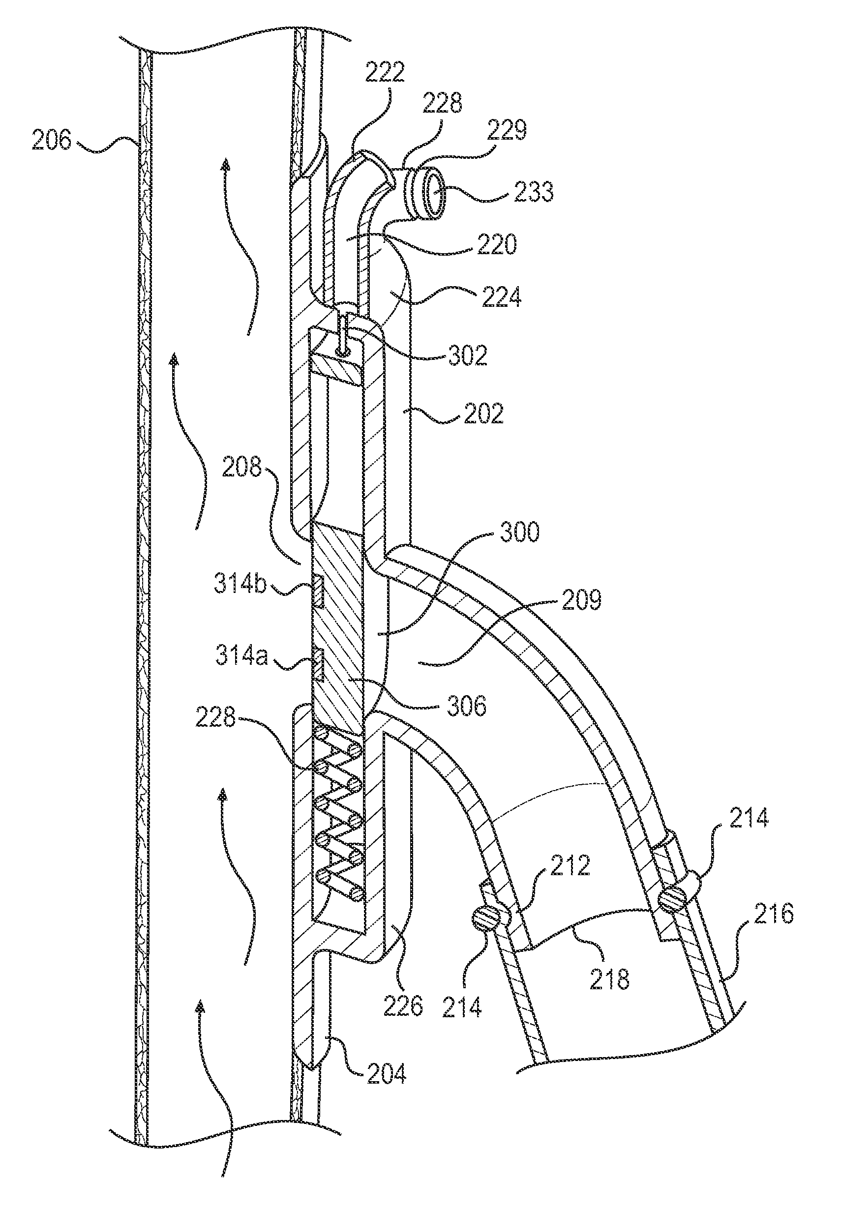
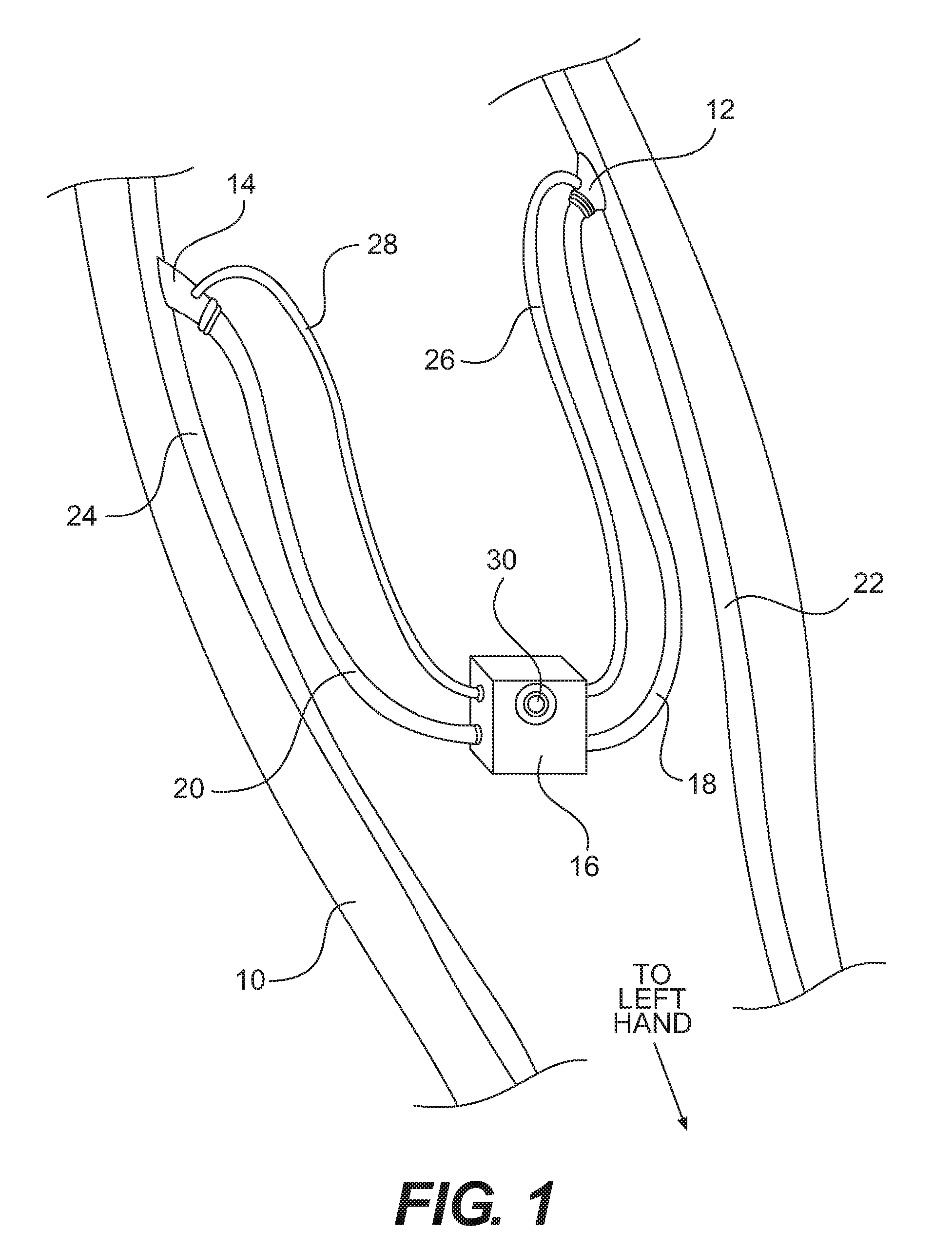
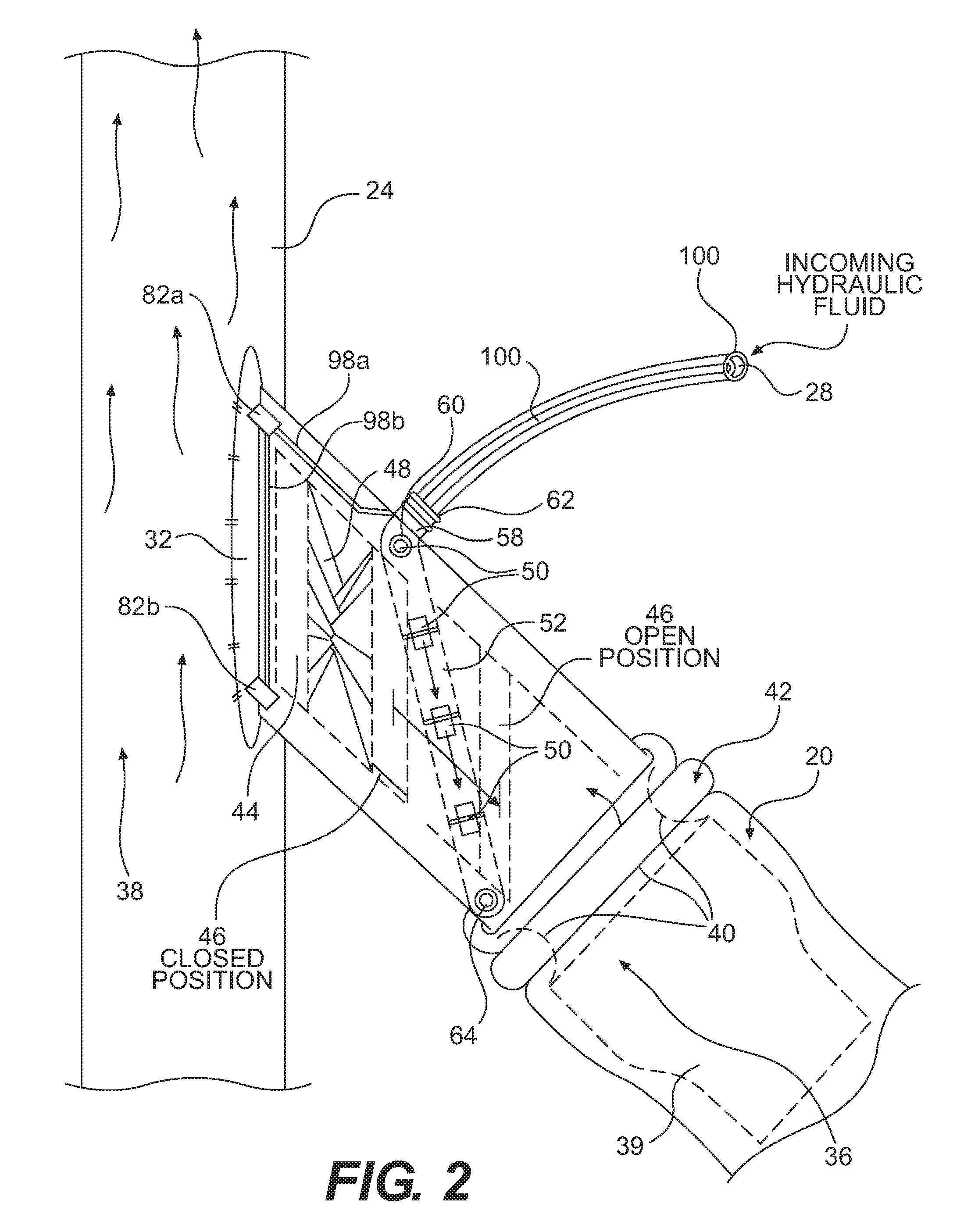
[0031]The present invention provides an arteriovenous shunt device for establishing hemodialytic angioacess. Devices operating according to a preferred embodiment of the present invention are capable of collecting and storing data concerning its own patency, and transmitting the data to an external receiver for further processing and analysis by medical technicians or practitioners. Some embodiments of the present invention have a modular design that includes at least two flexible shunts and one medial flow control unit. In embodiments having the modular design, the medial flow control unit is relatively easily connected between the two flexible shunts by the vascular surgeon during the implantation procedure. Because this embodiment of the device comprises at least three conjoined pieces instead of one, vascular surgeons have greater flexibility when it is determined during implantation and repair surgery that the overall length and / or arrangement of the shunt device needs to be sh...


PUM


Abstract

A hemodialytic angioacess device for implantation in dialysis patients, comprising an arteriovenous (AV) shunt, anastomotic valves that connect the AV shunt to blood vessels, a valve control system and an integrated surveillance system that measures flow conditions in the blood vessels at the AV shunt, preferably when the valves are closed and the patient is not undergoing dialysis treatment. The flow condition data, which may include data representing the flow rate, pressure, volume and velocity of blood flowing through the vessels, is stored in a memory and transmitted to a health care provider or technician on demand. The data can be used to calculate and monitor important physiological parameters, such as compliance and resistance, for the blood vessels, and help detect and identify dangerous conditions, such as turbulence and stasis, which can contribute to AV shunt failure, vessel injury and other serious complications for the patient.

Description

CROSS-REFERENCE TO RELATED APPLICATIONS[0001]This application is a continuation-in-part of U.S. application Ser. No. 12 / 189,669 (now U.S. Pat. No. 8,057,421), filed on Aug. 11, 2008, and claims the benefit of U.S. Provisional Application No. 60 / 954,910, filed on Aug. 9, 2007. application Ser. No. 12 / 189,669 and 60 / 954,910 are both incorporated into this application in their entirety by this reference.FIELD OF ART[0002]The present invention relates generally to devices and methods for performing hemodialysis for patients suffering from end-stage renal disease (ESRD). More particularly, the invention relates to implantable modular arteriovenous shunt systems, hemodialytic angioacess devices, a anastomotic valves for a hemodialytic angioacess devices, surveillance systems for a hemodialytic angioacess devices, and methods of using same for establishing hemodialytic angioaccess in hemodialysis patients.RELATED ART[0003]Hemodialysis is a method of removing waste products, such as potassi...

Claims


Application Information

Patent Timeline
Patent Type & Authority Patents(United States)
IPC IPC(8): A61M5/00
CPCA61M2001/3656A61B5/686A61B5/026A61B5/6876A61B2562/0247A61B2562/0271A61M1/3655A61M1/3656A61M1/3623
Inventor AKINGBA, AJIBOLA, GEORGE
Owner INDIANA UNIV RES & TECH CORP
Why Eureka
Try Eureka