Method and apparatus for allowing blood flow through an occluded vessel

a technology of occluded vessels and blood flow, applied in the field of medical devices, can solve the problems of tissue ischemia (lack of oxygen and nutrients), rapid development of tissue ischemia, and rapid progression of tissue infarction (cell death) to achieve the effect of preventing undeired radial force against the occlusion

Active Publication Date: 2010-12-16
PERFLOW MEDICAL
View PDF84 Cites 173 Cited by
  • Summary
  • Abstract
  • Description
  • Claims
  • Application Information

AI Technical Summary

Benefits of technology

[0012]In view of the discussion provided above and other considerations, the present disclosure provides methods and apparatuses for sustaining patency through an occlusion. This is accomplished in certain embodiments by providing a device arranged to provide and / or sustain at least partial patency of a small blood vessel exhibiting an occlusion. The device comprises a tubular body expandable from an initial small diameter state for manipulation adjacent, and / or through, the occlusion of the small blood vessel and a second large diameter state. In some embodiments, the second large diameter is limited to a maximal allowed value, thus preventing undesired radial force against the occlusion. Optionally, the second large diameter state is no more than 50% of the diameter of the blood vessel at the occlusion location. The term small blood vessel as used herein is defined as a blood vessel of 5 mm or less of inner diameter and may be constituted of an intracranial blood vessel.

Problems solved by technology

Stroke is a leading cause of disability, death and health care expenditure.
When an artery is obstructed, tissue ischemia (lack of oxygen and nutrients) quickly develops.
Ischemia will rapidly progress to tissue infarction (cell death) if the occlusion of blood flow persists.
The ischemic penumbra, although physiologically impaired, is potentially salvageable tissue, however the window of opportunity for recovery of the reversibly injured neurons in the ischemic penumbra is relatively short.
Failure to timely restore blood flow triggers a biochemical and metabolic cascade ultimately leading to irreversible brain injury by progressive transformation of the ischemic penumbra into infarcted tissue, i.e. the infarct core expands as the penumbra tissue experiences necrosis.
Achieving artery patency by any of these above methods or any combination of them (multimodal therapy) is often complex, requires multiple steps and is time consuming.
As a result, cells within this infarction zone will be irreversibly damaged within a few minutes.
Disadvantageously, the radial force required may traumatize the blood vessel exhibiting the occlusion.
Additionally, aggregation of the dislodged fragments in the capturing mesh disrupts and subsequently decreases the blood flow.
The requirement for inlet and outlet ports fails to take full advantage of the pressure differential between the proximal and distal sides of the occlusion.
Disadvantageously, the self expanding stent exerts radial force against the occlusion, which may result in undesired breaking up of the occlusion with significant fragments being dislodged to proceed further into the bloodstream resulting in potential brain damage.

Method used


Image

  • Method and apparatus for allowing blood flow through an occluded vessel
  • Method and apparatus for allowing blood flow through an occluded vessel
  • Method and apparatus for allowing blood flow through an occluded vessel

Examples


first embodiment

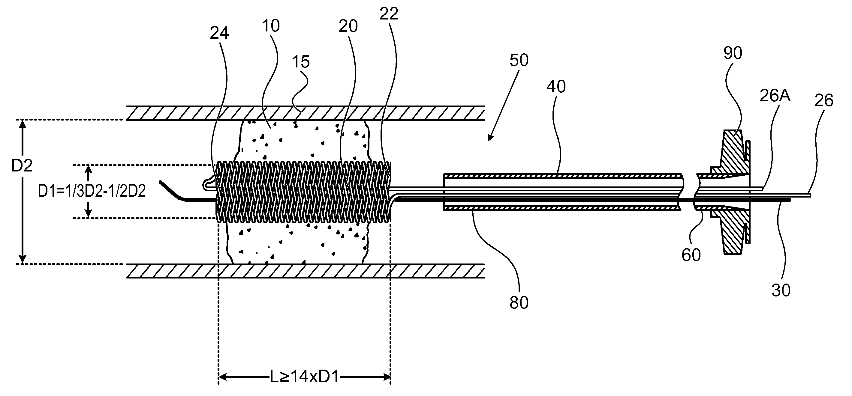
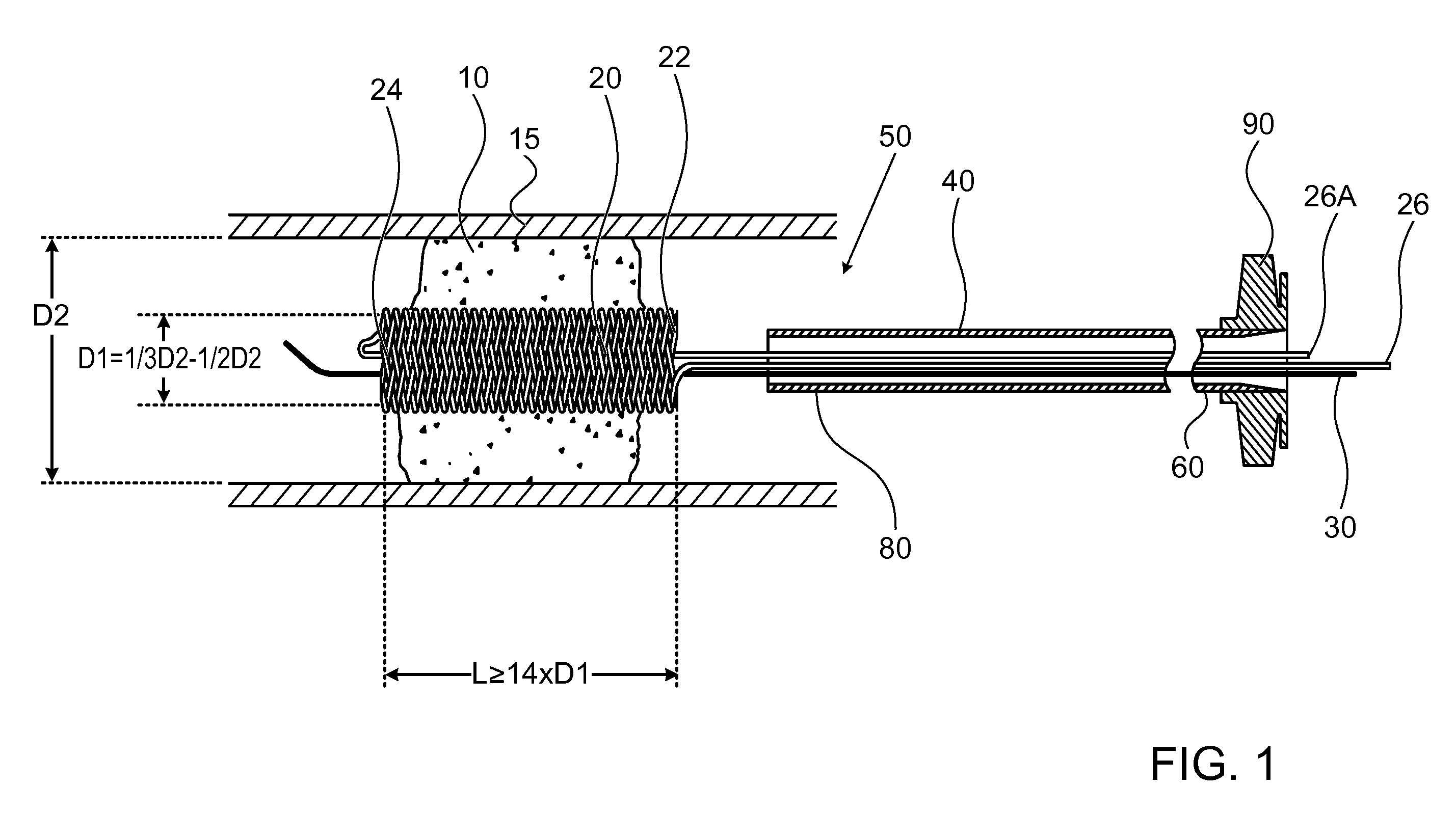
[0050]FIG. 1 illustrates a high level schematic diagram of a sectioned view of a temporary endovascular conduit system, denoted temporary endovascular conduit system 50, deployed in an occlusion 10 occluding a body lumen 15. Temporary endovascular conduit system 50 comprises: a catheter 40, exhibiting a proximal portion 60 and a distal portion 80; a hub 90; a pair of members 26 and 26A; a guide wire 30; and a self expanding device 20, exhibiting a proximal end 22 and a distal end 24, illustrated in a large diameter state. The diameter of body lumen 15 in the area of occlusion 10 is denoted D2, and the inner diameter of self expanding device 20 in the large diameter state, denoted D1, is preferably between ⅓ and ½ of D2. Body lumen 15 is a small blood vessel, exhibiting an inner diameter D2 of 5 mm or less, as described above. Advantageously, providing a conduit exhibiting an inner diameter for blood flow of at least ⅓ of D2 allows a sufficient blood flow, in the absence of sufficien...

second embodiment

[0070]FIG. 4 illustrates a high level schematic diagram of a sectioned view of a temporary endovascular perfusion conduit system, denoted temporary endovascular perfusion conduit system 150, deployed in an occlusion 10 occluding a body lumen 15. Temporary endovascular perfusion conduit system 150 comprises: a catheter 40, exhibiting a proximal portion 60 and a distal portion 80; a hub 90; a pair of members 126 and 126A; and an expanding device 120, exhibiting a proximal end 122 and a distal end 124, illustrated in a large diameter state. A guide wire 30 is also provided. The diameter of body lumen 15 in the area of occlusion 10 is denoted D2, and the inner diameter of expanding device 120 in the large diameter state denoted D1, is between ⅓ and ½ of D2. Advantageously providing a conduit exhibiting an inner diameter for blood flow of at least ⅓ of D2 allows a sufficient blood flow, in the absence of sufficient collateral flow from other arteries, to prevent or delay cell death since...


PUM


Abstract

A device arranged to sustain and/or provide at least partial patency of a small blood vessel exhibiting an occlusion, the device constituted of a tubular body expandable from a first small diameter state for manipulation to, and through, the occlusion of the small blood vessel and a second large diameter state, the inner dimensions of the second large diameter state being no more than 50% of the diameter of the small blood vessel at the occlusion location, the device presenting a conduit for blood flow through the occlusion when in the large diameter state. In one embodiment the small blood vessel is an intracranial blood vessel.

Description

BACKGROUND OF THE INVENTION[0001]The invention relates generally to the field of medical devices, specifically to medical devices that are useful in treating stroke, and more particularly to a device allowing for the flow of oxygenated blood through an obstructed artery thus sustaining at least partial patency.[0002]Stroke is a leading cause of disability, death and health care expenditure. Most strokes are ischemic, i.e. caused by a decrease in the blood supply to a portion of the brain due to a clot obstructing the flow of blood. A total or hemodynamically significant occlusion of a cerebral artery in an acute ischemic stroke is mostly due to thrombus formation, an embolus, and / or other unwanted matter. When an artery is obstructed, tissue ischemia (lack of oxygen and nutrients) quickly develops. The organ most sensitive to ischemia is the brain. Ischemia will rapidly progress to tissue infarction (cell death) if the occlusion of blood flow persists. In patients experiencing a typ...

Claims


Application Information

Patent Timeline
Patent Type & Authority Applications(United States)
IPC IPC(8): A61F2/82A61F2/86
CPCA61B17/221A61B17/320725A61B2017/00893A61B2017/22034A61B2017/2215A61F2/01A61F2230/0078A61F2/88A61F2250/0059A61M29/02A61F2220/005A61F2220/0058A61F2220/0075A61F2/86A61F2250/0098A61F2/844A61B90/39
Inventor RAPAPORT, AVRAHAMCIBULSKI, GILAD
Owner PERFLOW MEDICAL
Why Eureka
Try Eureka