Locator and delivery device and method of use

a technology of a locator and a delivery device, which is applied in the field of locators and delivery devices and methods of use, can solve the problems of time-consuming and expensive procedures, requiring as much as an hour of the physician's or nurse's time, and uncomfortable for patients

Inactive Publication Date: 2008-03-13
CARDINAL HEALTH SWITZERLAND 515 GMBH
View PDF99 Cites 189 Cited by
  • Summary
  • Abstract
  • Description
  • Claims
  • Application Information

AI Technical Summary

Benefits of technology

[0015] The device is also provided with an obturator in the lumen of the elongate member, which obturator has a relatively large diameter distal portion coupled to a shaft having a narrower diameter. The distal port in the elongate member is located proximally of the large diameter portion of the obturator. In this preferred embodiment, the distal portion of the obturator and the shaft have a common central lumen and an outer surface of the distal portion of the obturator is provided with a groove which is substantially parallel to the axis of the obturator. The device is also provided with a guidewire which passes through the groove on the external surface of the distal portion of the obturator and a tether which passes through the central lumen of the obturator. The guidewire has a specialized configuration at its distal end and is provided with an indicator means at its proximal region. These features facilitate the ability of the device to deploy the sealing element at a substantially precise location. Once this location is reached, the elongate member is withdrawn a short distance and the obturator is held stationary to eject the sealing element from the elongate member.
[0018] Next, the device and sheath are withdrawn together a short distance such that the distal port is no longer within the lumen of the femoral artery and the flow of blood is substantially blocked from reaching the distal port by the patient's tissue and the sealing element.
[0020] The disc attached to the guidewire and the disc attached to the delivery tube are spaced a short distance apart and permit a more precise positioning of the sealing element than would otherwise be possible. It is to be noted, however, that the use of such discs is preferred, but that other structures can be used to accomplish the same purpose.

Problems solved by technology

This procedure, however, may be time consuming and expensive, requiring as much as an hour of a physician's or nurse's time.
It is also uncomfortable for the patient, and requires that the patient remain immobilized in the operating room, catheter lab, or holding area.
In addition, a risk of hematoma exists from bleeding before hemostasis occurs.
Such devices, however, may be difficult to position properly with respect to the vessel, which may be particularly significant since it is generally undesirable to expose the plug material, e.g., collagen, within the bloodstream, where it may float downstream and risk causing an embolism.
Percutaneous suturing devices, however, may require significant skill by the user, and may be mechanically complex and expensive to manufacture.
These staples, however, have a large cross-sectional profile and therefore may not be easy to deliver through a percutaneous site to close an opening in a vessel wall.
Such plugs, however, may only be used at the surface of the skin, and may not be introduced through tissue, for example, to seal an opening in the wall of a blood vessel or other subcutaneous region.
However, prior bleed back devices have been constructed such that blood flow out of the patient continues for a longer period of time during deployment of the sealing means than would be desirable.

Method used


Image

  • Locator and delivery device and method of use
  • Locator and delivery device and method of use
  • Locator and delivery device and method of use

Examples


Embodiment Construction

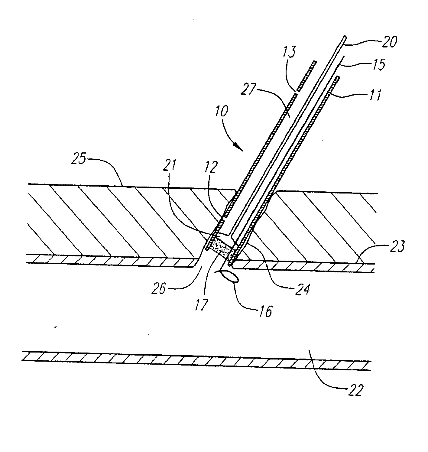
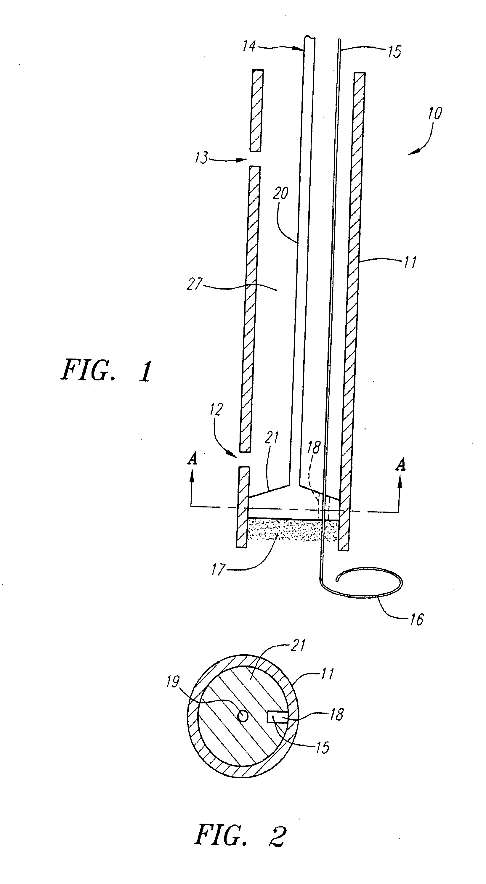
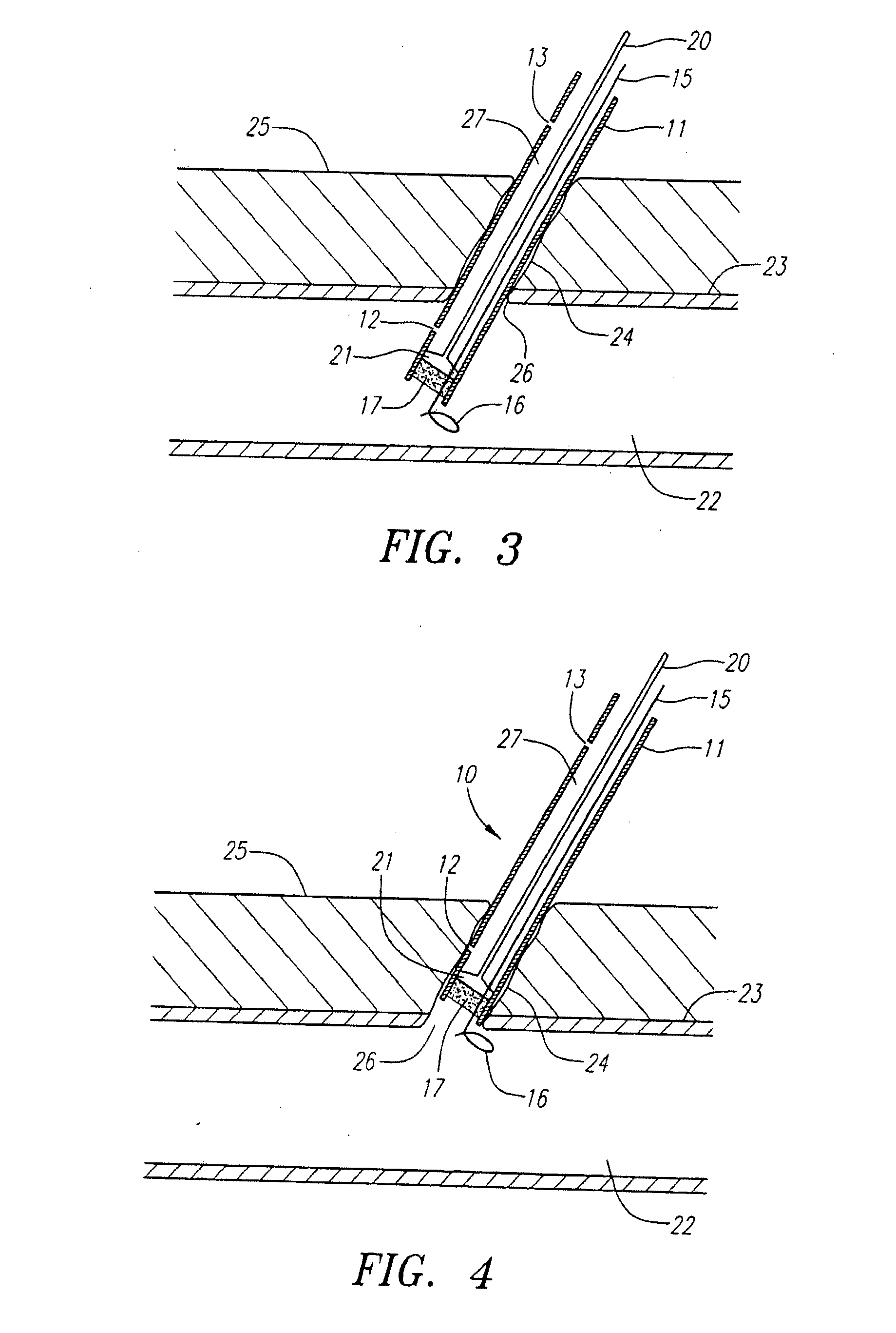
[0039]FIG. 1 illustrates in a somewhat schematic form many of the features of the device of the present invention. The device 10 includes a delivery tube 11 which is provided with a distal port 12 and a proximal port 13. An obturator 14 is housed within the delivery tube 11 and comprises a shaft 20 and a larger diameter distal portion 21. The device 10 is also provided with a guidewire 15 which has a transversely extending distal portion 16. The device is also provided with a sealing element 17 which is preferably formed from a felt, hydrogel, or other material suitable for use in sealing punctures or other openings communicating with body lumens, such as blood vessels.

[0040]FIG. 2 is a cross-sectional view of the device shown in FIG. 1 taken on line A-A. As can be seen from FIG. 2, the distal portion 21 of the obturator 14 is provided with a groove 18 which serves as a passageway for the guidewire 15. In addition, the obturator 14 is provided with a lumen 19 (not shown in FIG. 1) ...


PUM


Abstract

This invention relates to apparatus and methods for use in sealing a vascular puncture site and to apparatus and methods for properly locating and deploying a sealing device. The locating apparatus comprises a lumen which extends from an opening in the distal region of the apparatus but located proximally of the sealing device, which lumen extends to another opening in the proximal region of the device. When the distal opening is in communication with blood in a blood vessel, blood flow through the lumen and out of the proximal opening signifies such location to the user. When the sealing device is withdrawn such that the sealing device is deployed such that it blocks the blood flow into the distal port, the user will know the location of the sealing device. In a preferred embodiment, the sealing device is then withdrawn proximally a predetermined distance to assure that no part of the sealing device extends into the blood vessel lumen. The sealing device is then detached from the delivery device.

Description

RELATED APPLICATION [0001] This patent application is a continuation of U.S. patent application Ser. No. 10 / 850,795 which is a continuation-in-part of U.S. patent application Ser. No. 10 / 687,848 filed on Oct. 17, 2003, the disclosures of which are incorporated by reference herein.FIELD OF THE INVENTION [0002] The present invention relates generally to apparatus and methods for sealing or closing passages through tissue, and more particularly to devices for sealing punctures or other openings communicating with body lumens, such as blood vessels, and to apparatus and methods for delivering such devices. BACKGROUND OF THE INVENTION [0003] Catheterization and interventional procedures, such as angioplasty or stenting, generally are performed by inserting a hollow needle through a patient's skin and muscle tissue into the vascular system. A guide wire may then be passed through the needle lumen into the patient's blood vessel accessed by the needle. The needle may be removed, and an int...

Claims


Application Information

Patent Timeline
Patent Type & Authority Applications(United States)
IPC IPC(8): A61B17/08A61B17/00A61B17/22A61B19/00
CPCA61B17/0057A61B2017/00004A61B2017/00022A61B2017/00637A61B2017/0065A61B2019/5251A61B2017/00672A61B2017/22047A61B2019/462A61B2019/4857A61B2017/00654A61B2090/062A61B2090/0811A61B2034/2051
Inventor GINN, RICHARD S.
Owner CARDINAL HEALTH SWITZERLAND 515 GMBH
Why Eureka
Try Eureka