Circuit for and a method of sensing a property of light

a technology of circuits and properties, applied in the direction of electric variable regulation, process and machine control, instruments, etc., can solve the problems of mismatch between actual color perception and desired color perception, the temperature of the heated part cannot be controlled, and the desired color and brightness cannot be obtained. , to achieve the effect of improving the control of the temperature of the heated part and increasing the temperature of the first circuit elemen

Inactive Publication Date: 2014-02-18
SIGNIFY HLDG BV +1
View PDF9 Cites 49 Cited by
  • Summary
  • Abstract
  • Description
  • Claims
  • Application Information

AI Technical Summary

Benefits of technology

[0016]In order to increase the temperature of the first circuit element, various measures, ranging e.g. from a heating resistor to a hot air fan, might be applied. However, these measures only allow a propagation of heat from the outside to the inside of the first circuit element and therefore a delay between the generation of the heat and its impact is intrinsic. Hence, in a preferred embodiment of the invention, the second circuit element comprises a current source that is designed to apply a current to the first circuit element. In the case of a photodiode or a phototransistor the current applied is the forward current of the junction of said photodiode or phototransistor. The (forward) current in fact allows directly heating up the first circuit element at its internal temperature-sensitive structure where the current flow takes place. Therefore, it further allows better control of the temperature of that part of the first circuit element that will be used—directly or indirectly—for sensing the property of light. In comparison to indirect heating of the inner structure of the first circuit element from the outside via the second circuit element, direct heating by means of the applied current also improves control of the temperature of the heated part of the first circuit element.

Problems solved by technology

The requirement to control the color point is basically triggered by various inherent problems related to the LEDs used in such a luminary.
Therefore the quality of the light produced by the LED luminary can vary significantly and the desired color and the demanded brightness of the light cannot be obtained without suitable feedback systems.
In this context, one of the big challenges is to correctly represent the effect of wavelength drift in the light emitted by the luminary.
But also ambient light that is not perfectly shielded from the sensor's photodiode might disturb the sensor's measurements and consequently leads to a mismatch between the actual color perception and the desired color perception.
The situation turns even worse if the sensor is used to achieve a constant illumination in a certain location while ambient light or contributions from other light sources influence the integral measurements obtained by the simple photodiode.
However, the pricing target for the LED luminary does not allow the use of such spectrometers.
Although this solution achieves desired results in terms of color control, its realization still requires a significant number of sensor elements in combination with appropriately realized and manufactured filters, which in total does not allow a cost efficient and compact design.

Method used


Image

  • Circuit for and a method of sensing a property of light
  • Circuit for and a method of sensing a property of light
  • Circuit for and a method of sensing a property of light

Examples


Embodiment Construction

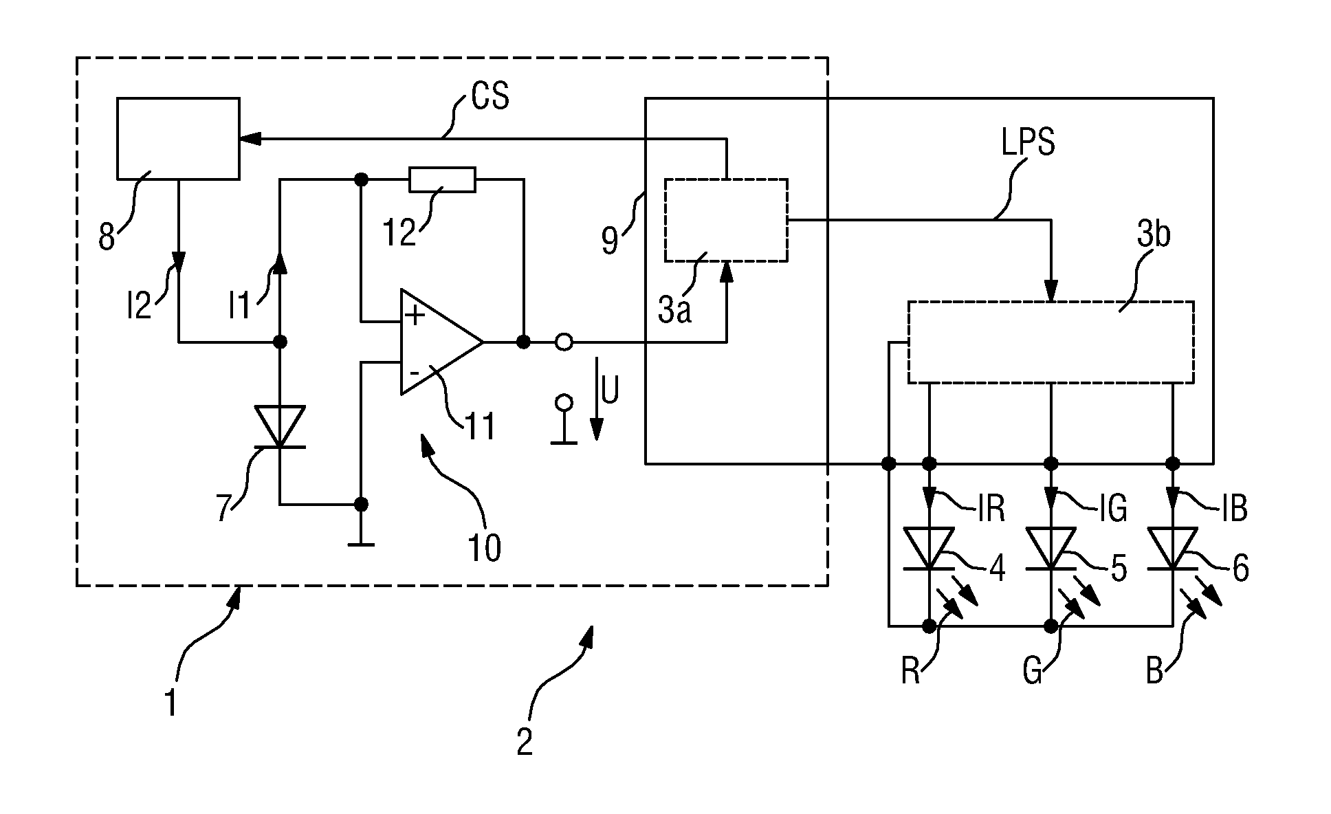
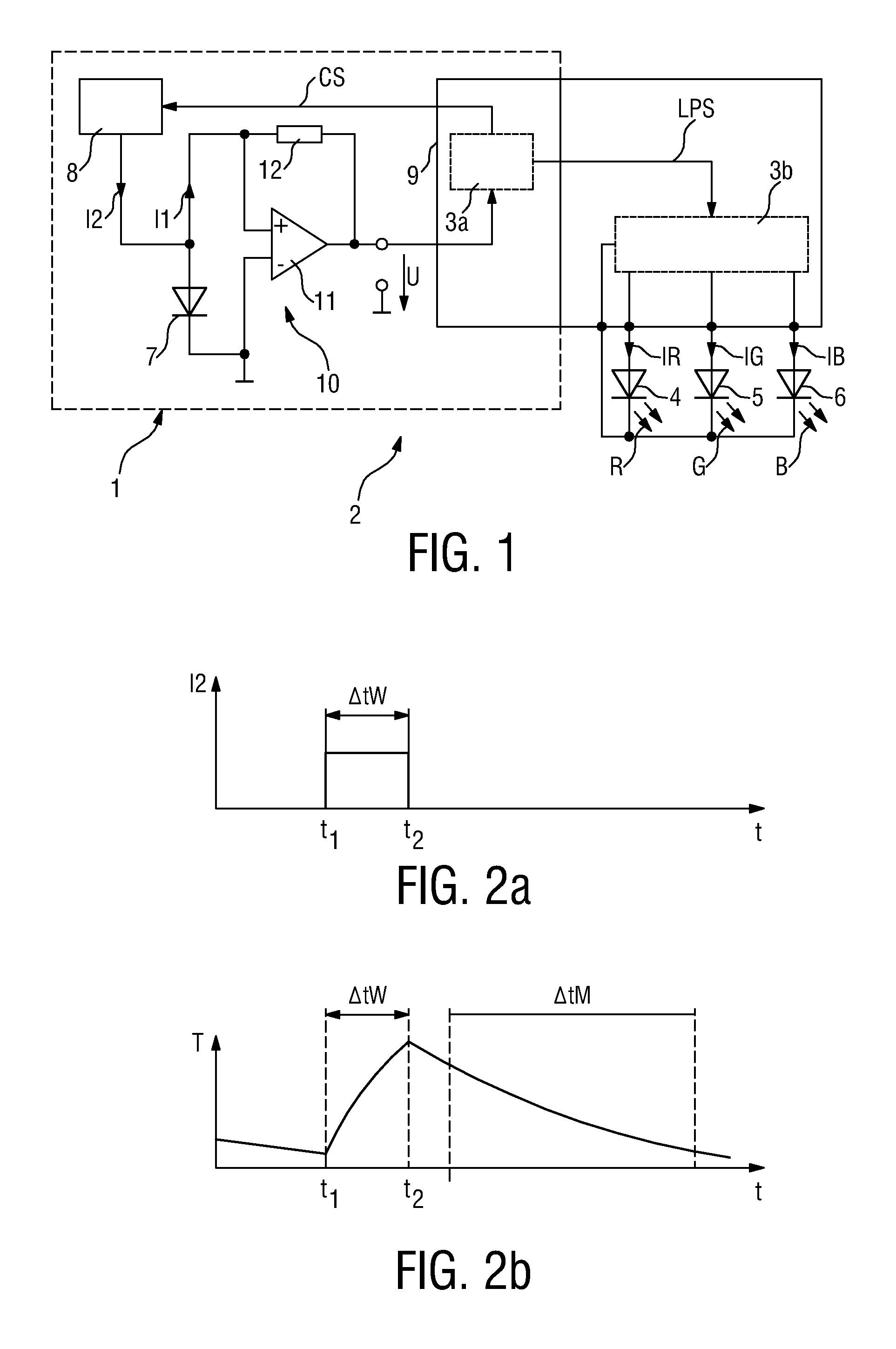
[0034]FIG. 1 shows a circuit 1 for sensing a property of light. The circuit 1 is used in a light emitting diode (LED) luminary 2. Such a LED luminary 2 may also be termed LED lamp. The luminary 2 comprises in addition to the circuit 1 a driver module 3b connected to a first LED 4 realized to emit red light R and a second LED 5 realized to emit green light G and a third LED 6 realized to emit blue light B. The driver module 3b is comprised in a controller 9, which in the present case is realized by means of a programmable device having signal processing-, data storage-, and LED driving-capabilities. Based on these controller features the driver module 3b is realized to generate driving-currents IR, IG, and IB, each for driving the respective LED 4, 5 and 6 in order to generate light having a particular intensity and causing a certain color impression at the human's eye. The setting of the driving-currents IR, IG, and IB is determined in dependency on the sensing response of the circu...


PUM


Abstract

In a circuit (1) for sensing a property of light there are provided a first circuit element (7) that is sensitive to light and that is realized to generate an output signal (I1) during a measurement time period (ΔtM), wherein the output signal (I1) is generated according to light to which the first circuit element (7) is exposed and the temperature (T) of the first circuit element (7), and a second circuit element (8) that is realized to increase the temperature (T) of the first circuit element (7) during a warming time period (ΔtW) that precedes the measurement time period (ΔtM).

Description

FIELD OF THE INVENTION[0001]The invention relates to a circuit for sensing a property of light.[0002]The invention further relates to a method of sensing a property of light.BACKGROUND OF THE INVENTION[0003]In the field of color tunable multi LED luminaries or multi LED lamps, color control is a crucial topic in order to achieve and maintain color point accuracy. Color points or, more generally, colors are quantified by chromaticity coordinates, of which the most widely used are the CIE (Commission International de l'Eclairage) 1931 chromaticity coordinates. Here the combination of x and y defines the color and L defines the brightness, i.e. luminosity, of the light. This system is based on the response of the eye of the average observer and is the internationally accepted standard. The requirement to control the color point is basically triggered by various inherent problems related to the LEDs used in such a luminary. For example, the optical characteristics of individual LEDs var...

Claims


Application Information

Patent Timeline
Patent Type & Authority Patents(United States)
IPC IPC(8): H05B37/02G05F1/00H05B39/04H05B41/36H05B44/00
CPCH05B33/0869H05B33/0872H05B33/0818H05B45/22H05B45/20H05B47/10Y02B20/30
Inventor RADERMACHER, HARALD JOSEF GUNTHERMARTINY, CHRISTOPH
Owner SIGNIFY HLDG BV
Why Eureka
Try Eureka