Wireless image transmission device

a transmission device and wireless technology, applied in the field of wireless image transmission devices, can solve the problems of imposing a limitation on photographing distance, unable to remove the lens from the electronic device, and the lens cannot serve as a stand-alone devi

Inactive Publication Date: 2014-02-18
CHEN YUNG CHIEN
View PDF6 Cites 11 Cited by
  • Summary
  • Abstract
  • Description
  • Claims
  • Application Information

AI Technical Summary

Benefits of technology

[0008]An object of the present invention is to provide a wireless image transmission device, which comprises a structure that allows a lens body and an electronic device to selectively separate from or couple to each other, wherein the lens body comprises a transmitter unit and the electronic device comprises a receivers unit so that wireless transmission of images can be effected, whereby when the lens body is separate from the electronic device, the electronic device can receive images taken by the lens body in a wireless manner.

Problems solved by technology

(1) Although the electronic device is provided with a lens, a user must properly hold the electronic device with hands to effect focusing and photographing. This imposes a limitation to photographing distance.
(2) The lens is fixed to the electronic device and is electrically connected a control circuit internally of the electronic device. This makes it impossible to remove the lens from the electronic device.
(3) After being removed, the lens cannot serve as a stand-along device and is incapable of wireless transmission of images.

Method used


Image

  • Wireless image transmission device
  • Wireless image transmission device
  • Wireless image transmission device

Examples


first embodiment

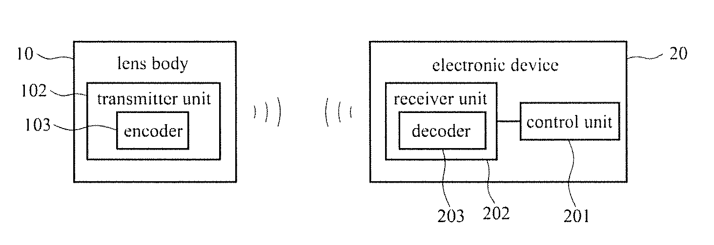
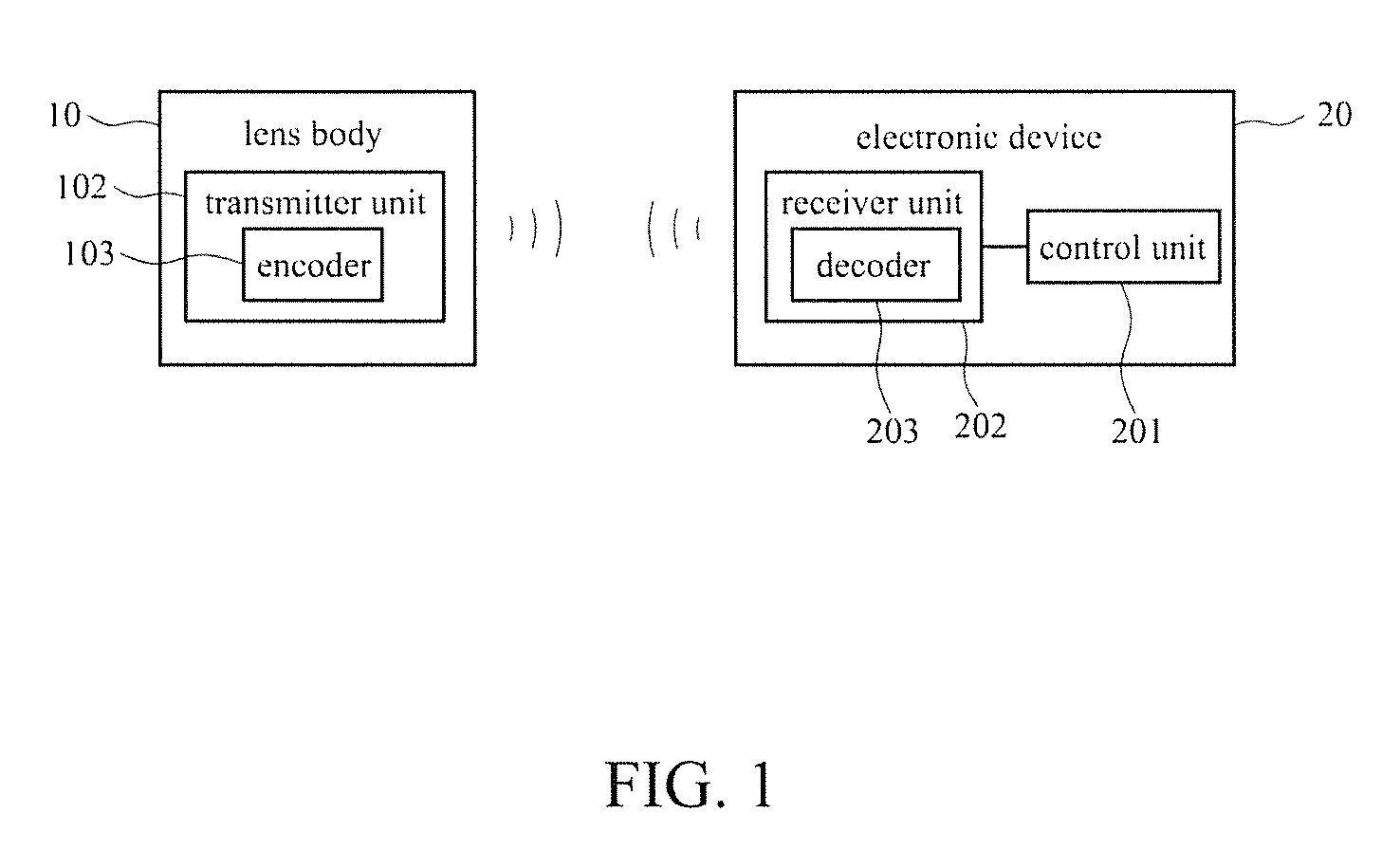
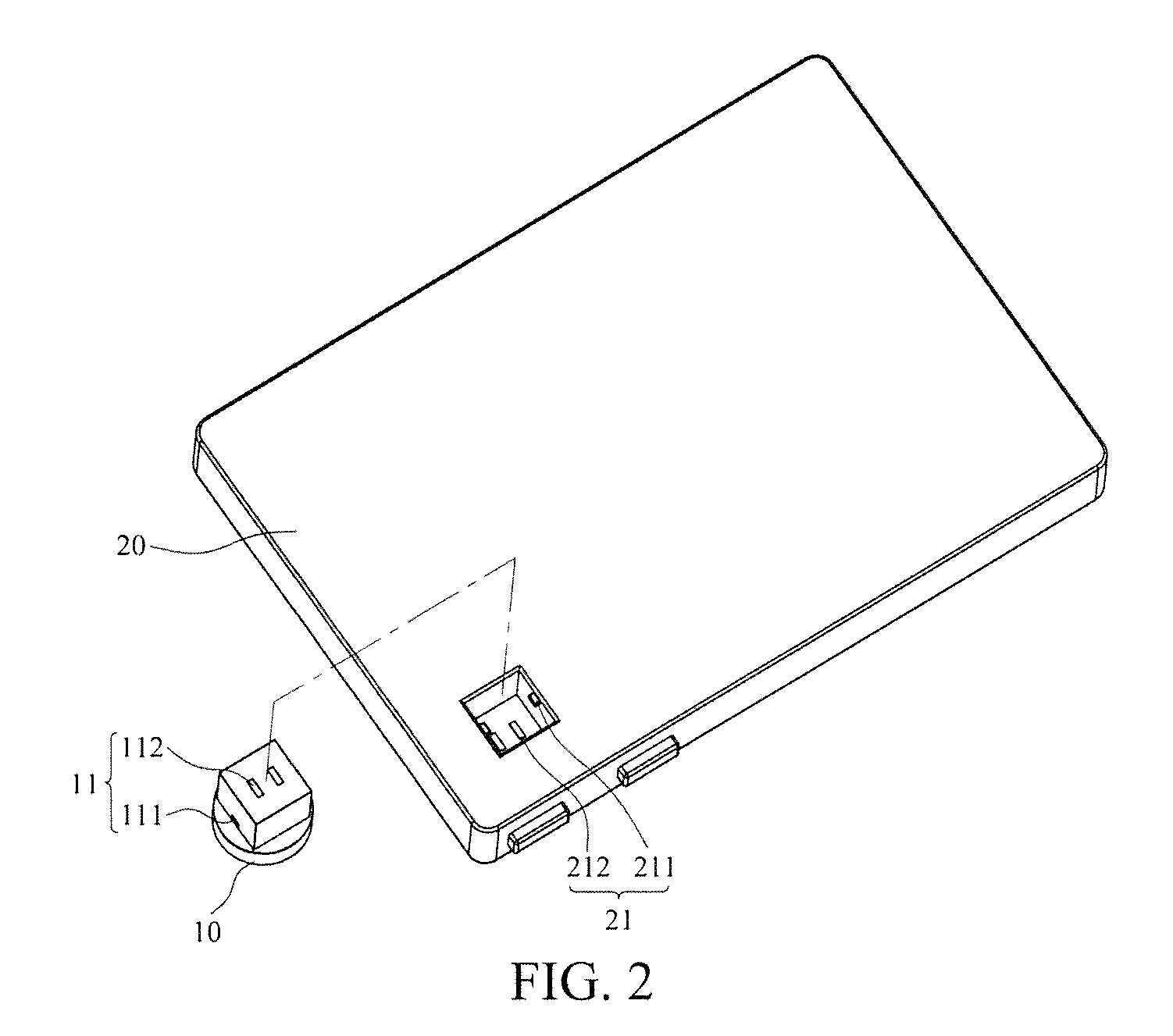
[0022]With reference to the drawings and in particular to FIGS. 1-5, a wireless image transmission device comprises a lens body 10, to which a lens 101 is mounted. The lens body 10 comprises a transmitter unit 102 mounted therein. The transmitter unit 102 comprises an encoder 103. The encoder 103 functions to provide an encoded signal of wirelessly transmitted images. The lens body 10 has an end forming a first connection section 11. An electronic device 20 comprises a control unit 201 and a receiver unit 202. The control unit 201 is electrically connected to a receiver unit 202. The receiver unit 202 comprises a decoder 203. The decoder 203 functions to wirelessly receive and convert the encoded signal of images from the transmitter unit into a decoded image signal and transmit the decoded image signal to the control unit 201. The electronic device 20 has an end forming a second connection section 21. The second connection section 20 is connectable to the first connection section 1...

second embodiment

[0025]Referring to FIG. 6, with additional reference to FIG. 1-5, the second embodiment is different from the first embodiment in that the solution of separation and coupling between the lens body 10 and the electronic device 20 is different. Repeated description will be omitted herein. In FIG. 6, the first connection section 12 has two sides each of which forms a slide channel 121. Further, the first connection section 12 forms on one side thereof a positive electrode engagement recess section 122 and the first connection section 12 also forms on another side thereof a negative electrode engagement recess section 123. The second connection section 22 has two inside surfaces each forming a slide rail 221. The second connection section 22 forms in one inside surface thereof a positive electrode engagement projection section 222 and the second connection section 22 forms in another inside surface thereof a negative electrode engagement projection section 223. With the slide rails 221 ...

third embodiment

[0026]Referring to FIG. 7, with additional reference to FIG. 1-5, the second embodiment is different from the first embodiment in that the solution of separation and coupling between the lens body 10 and the electronic device 20 is different. Repeated description will be omitted herein. In FIG. 7, the first connection section 13 has an outer circumference forming a male thread 131 and the first connection section 13 has a bottom forming a positive / negative electrode terminal 132. The second connection section 23 has an inside surface forming a female thread 231 and the second connection section 23 has a bottom forming a positive / negative electrode coupling section 132. With the male thread 131 of the first connection section 13 engaging the female thread 231 of the second connection section 23, the positive / negative electrode terminal 132 of the first connection section 13 is coupled to the positive / negative electrode coupling section 132 of the second connection section 23. As such...


PUM


Abstract

The present invention provides a wireless image transmission device, which includes a lens body which a lens is mounted. The lens body includes a transmitter unit that includes an encoder functioning to provide an encoded signal of wirelessly transmitted images. The lens body has an end forming a first connection section. An electronic device includes a control unit electrically connected to a receiver unit that includes a decoder functioning to wirelessly receive and convert the encoded signal of images from the transmitter unit into a decoded image signal to be applied to the control unit. The electronic device has an end forming a second connection section. The second connection section is connectable to the first connection section of the lens body. When the lens body is separated from the electronic device, the electronic device can receive image taken by the lens body in a wireless manner.

Description

FIELD OF THE INVENTION[0001]The present invention relates to a wireless image transmission device, and in particular to a structure that allows a lens body to be separate from and re-mounted to an electronic device, wherein the lens body comprises a transmitter unit and the electronic device comprises a receiver unit so that when the lens body is separate from the electronic device, the electronic device may receive, in a wireless manner, images taken by the lens body.BACKGROUND OF THE INVENTION[0002]The development of science and technology allows various electronic devices (such as mobile phones, smart phones, and tablet computers) to be combined with an image photographing function, in addition to the ordinary digital cameras and camcorders that are commonly used to shoot pictures or to photograph.[0003]These electronic devices are structured to embed a lens in a device body so that the lens can be used to take images. However, there are drawbacks:[0004](1) Although the electroni...

Claims


Application Information

Patent Timeline
Patent Type & Authority Patents(United States)
IPC IPC(8): G03B17/14
CPCG03B17/14H04M1/0256H04M1/0264H04N5/2251H04N5/2257H04N23/57H04N23/55
Inventor CHEN, YUNG-CHIEN
Owner CHEN YUNG CHIEN
Why Eureka
Try Eureka