Liquid jetting apparatus
a technology of liquid jetting apparatus and liquid, which is applied in printing and other directions, can solve the problems of increased cost and consequent increase of electric power consumption, and achieve the effects of enhancing energy efficiency, reducing cost and effective utilization
- Summary
- Abstract
- Description
- Claims
- Application Information
AI Technical Summary
Benefits of technology
Problems solved by technology
Method used
Image
Examples
first modified embodiment
[0103][First Modified Embodiment]
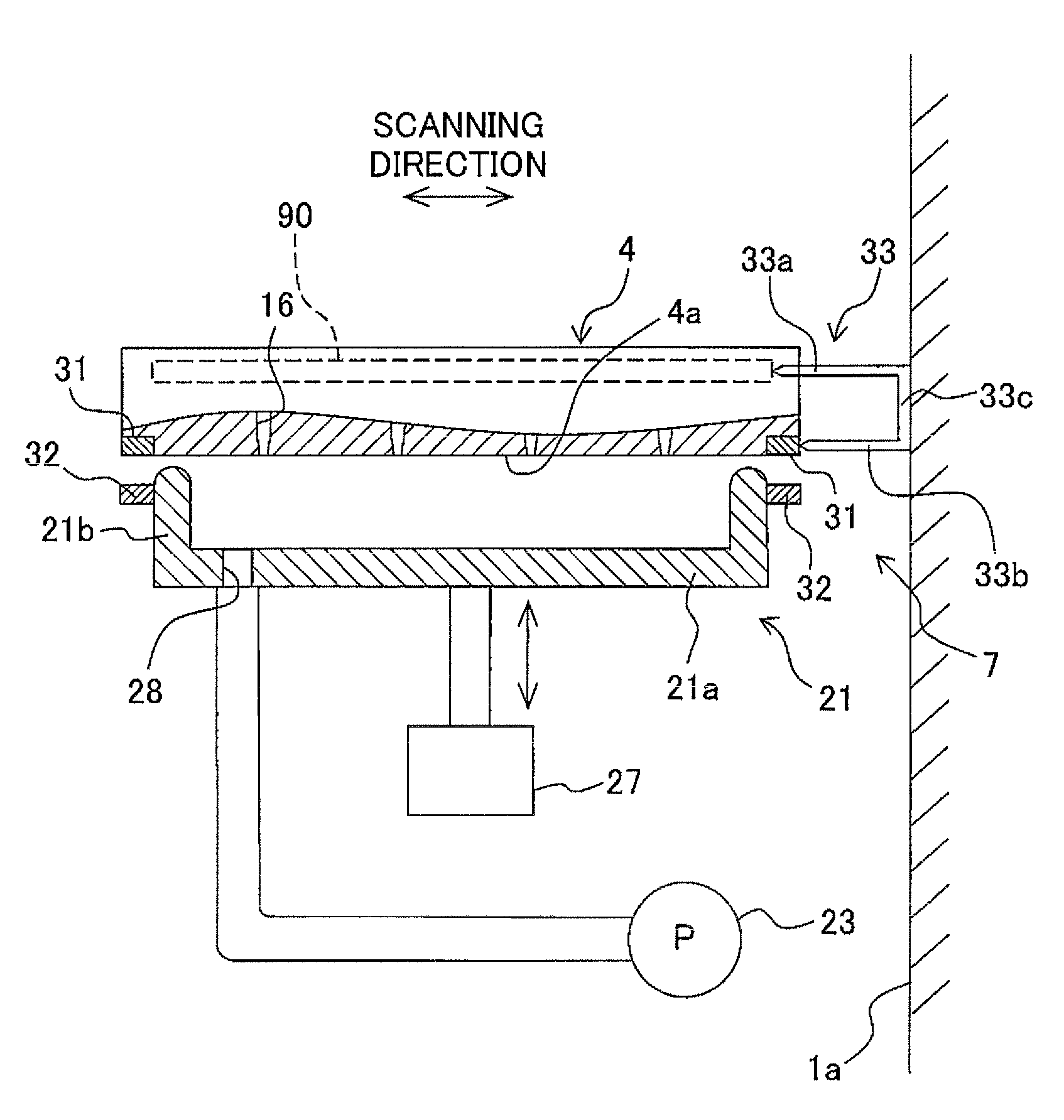
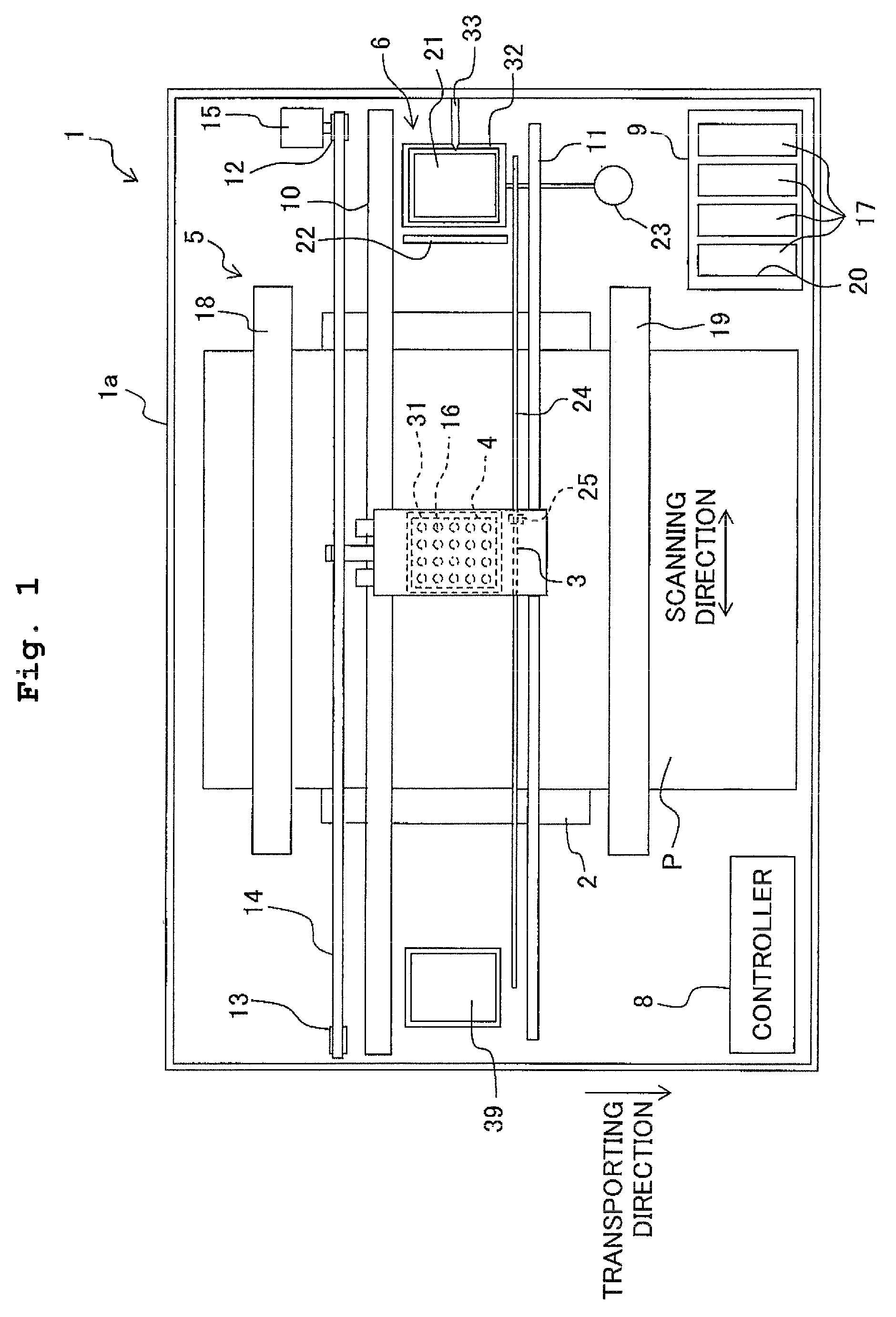
[0104]In the embodiment described above, the second electrode 32 is provided on the cap member 21 which is movable to make separation and approach with respect to the ink-jetting surface 4a, in relation to the structure or arrangement for allowing the second electrode 32 to make approach with respect to the first electrode 31 which is provided on the ink-jet head 4. However, the second electrode 32 may be provided on any member other than the cap member 21.
[0105]For example, as shown in FIG. 10A, a first electrode 131 is provided on a side surface of an ink jethead 104 disposed on the side of the liquid receiving member 39 in relation to the scanning direction. A second electrode 132 is fixed to an inner wall surface of the casing la disposed on the side of the liquid receiving member 39 in relation to the scanning direction, and the second electrode 132 is retained at the ground electric potential. Further, a dielectric 134 is arranged on a surface ...
second modified embodiment
[0110][Second Modified Embodiment]
[0111]As shown in FIG. 11, another modified embodiment is available in addition to the first modified embodiment described above, wherein a first electrode 235 is provided on a side surface of an ink-jet head 204 disposed on the side of the cap member 21 in relation to the scanning direction, in addition to the first electrode 131. That is, the first electrodes 131, 235 are provided on the both sides in the scanning direction of the ink-jet head 204. Further, a second electrode 236 is fixed to the inner wall surface of the casing 1a disposed on the side of the cap member 21 in relation to the scanning direction, in addition to the second electrode 132, and the second electrode 236 is retained at the ground electric potential. That is, the second electrodes 132, 236 are provided on the inner wall surfaces of the casing 1a disposed on the both sides in relation to the scanning direction. A dielectric 237 is arranged on a surface of the second electrod...
third modified embodiment
[0115][Third Modified Embodiment]
[0116]In the embodiment described above, a part of the electric current, which is provided when the ink-jet head 4 is driven during the flushing, is recovered to drive the mist adsorbing device 7. However, a part of the electric current, which is provided when the ink-jet head 4 is driven during the recording operation for jetting the inks to the recording paper P, may be recovered to drive the mist adsorbing device 7. However, during the recording operation, the ink-jet head 4 is moved in the scanning direction. It is difficult to accumulate the electric charge while maintaining a state in which the first electrode-provided on the ink-jet head 4 and the second electrode 32 are disposed closely to one another. In view of the above, it is also appropriate to provide a charging circuit for the electric current recovery circuit as explained below.
[0117]For example, as shown in FIG. 12, a electric current recovery circuit 393 has a switch 394 and an elec...
PUM
 Abstract
Description
Claims
Application Information
 - R&D
- Intellectual Property
- Life Sciences
- Materials
- Tech Scout
- Unparalleled Data Quality
- Higher Quality Content
- 60% Fewer Hallucinations
Browse by: Latest US Patents, China's latest patents, Technical Efficacy Thesaurus, Application Domain, Technology Topic, Popular Technical Reports.
© 2025 PatSnap. All rights reserved.Legal|Privacy policy|Modern Slavery Act Transparency Statement|Sitemap|About US| Contact US: help@patsnap.com


