Method and system for correctly identifying specific RFID tags

a radio frequency identification and correct identification technology, applied in the field of radio frequency identification systems, can solve the problems of difficult to achieve, difficult to read the code, etc., and achieve the effect of avoiding the problem of non-directivity to the rfid scan

Active Publication Date: 2014-02-25
VOCOLLECT
View PDF412 Cites 771 Cited by
  • Summary
  • Abstract
  • Description
  • Claims
  • Application Information

AI Technical Summary

Problems solved by technology

While UPC codes and scanners to read such codes provide a convenient system for capturing inventory information, such a system has several drawbacks.
This may be difficult to achieve when lining up the scanner with the UPC code.
Additionally, UPC codes on products or packaging can be damaged or marked up so that reading the code becomes nearly impossible.
Such non-directivity to the RFID scan, however, presents another issue.
One drawback of current RFID reader systems is that several RFID tags will be read when they are within the range of the RFID reader.
If the specific RFID tag on the removed product cannot be determined, then the RFID reader will not be able to communicate meaningful information to a centralized inventory system.

Method used


Image

  • Method and system for correctly identifying specific RFID tags
  • Method and system for correctly identifying specific RFID tags
  • Method and system for correctly identifying specific RFID tags

Examples


example a

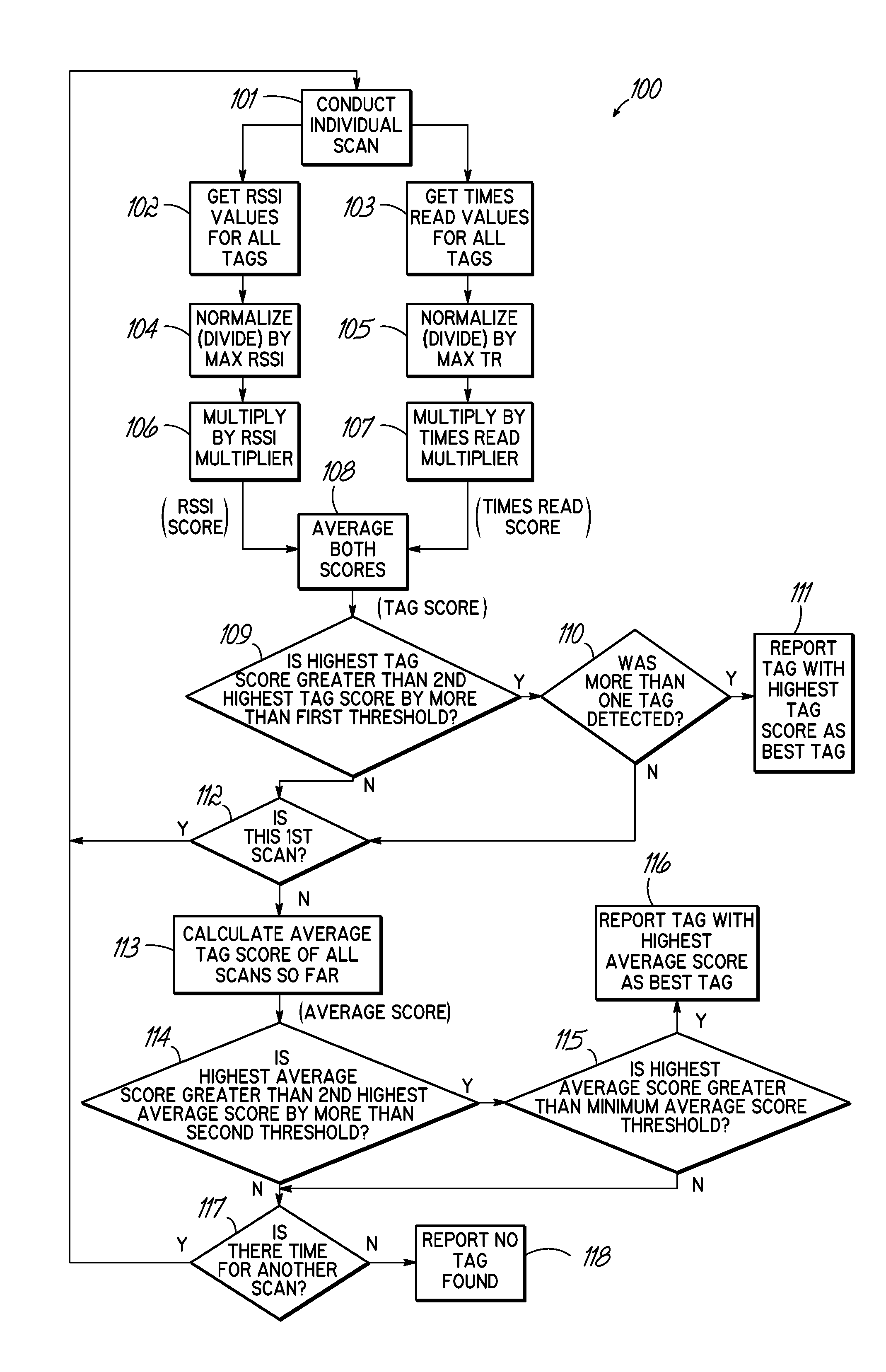
[0041]In the first case, the first individual scan at step 101 of the control algorithm 100 reports the following information: Tag A was detected with an RSSI value of 100 and a Times Read value of 20, while Tag B was detected with an RSSI value of 80 and a Times Read value of 5. At step 104, the RSSI values are normalized by dividing each RSSI value by the maximum RSSI value, which is 100 in this example. Therefore, the normalized RSSI values are 1.0 and 0.8. At step 105, the Times Read values are also normalized by dividing each Times Read value by the maximum Times Read value, which is 20 in this case. Therefore, the normalized Times Read values are 1.0 and 0.25. These steps provide Tag A with a normalized RSSI of 1.0 and a normalized Times Read of 1.0, and Tag B with a normalized RSSI of 0.8 and a normalized Times Read of 0.25. At steps 106 and 107, the normalized values are further emphasized by multiplying them by the respective RSSI multiplier and Times Read multiplier. This ...

example b

[0042]In the second case, the first individual scan at step 101 of the control algorithm 100 reports the following information: Tag A was detected with an RSSI value of 100 and a Times Read value of 20, while the next highest tag, Tag B, was detected with an RSSI value of 80 and a Times Read value of 10. At step 104, the RSSI values are normalized by dividing each RSSI value by the maximum RSSI value, which is 100 in this case. At step 105, the Times Read values are normalized by dividing each Times Read value by the maximum Times Read value, which is 20 in this case. These steps provide Tag A with a normalized RSSI of 1.0 and a normalized Times Read of 1.0, and Tag B with a normalized RSSI of 0.8 and a normalized Times Read of 0.5. At steps 106 and 107, the normalized values are emphasized by multiplying them by the respective RSSI multiplier and Times Read multiplier. This provides Tag A with an RSSI score of 0.8 and a Times Read score of 1.2, while Tag B has an RSSI score of 0.64...


PUM


Abstract

A system and method for identifying a specific RFID tag includes RFID reader circuitry, such as within an RFID reader, configured for sending and receiving RF signals to detect RFID tags and for obtaining signal parameter information associated with the RFID tags. Processing circuitry is configured for using the signal parameter information for one or more tags of the RFID tags and calculating a tag score for the one or more RFID tags. The processing circuitry is further configured for determining a specific RFID tag using the tag scores for the one or more RFID tags.

Description

TECHNICAL FIELD[0001]This invention relates generally to systems for reading radio frequency identification (RFID) tags, and more specifically, to a system that can identify a specific RFID tag on a product in the vicinity of other RFID tags.BACKGROUND[0002]Storage and management of inventory is a critical function of many businesses, including the manufacturing, retail, and shipping industries. For efficiency purposes, it is desirable to communicate product information to a centralized inventory tracking system as the product is being removed or placed on shelves, rather than requiring a separate entry of product information at a central location after removal or placement of the product.[0003]One conventional method for communicating product information to an inventory tracking system includes UPC bar codes that are placed on the products and portable bar code scanners that are carried by the workers manipulating the product. Portable bar code scanners are typically plugged in as ...

Claims


Application Information

Patent Timeline
Patent Type & Authority Patents(United States)
IPC IPC(8): H04Q5/22
CPCG06K7/10128G06Q10/087G06K7/10079G06K7/0008G06K7/10297G06K7/10039G06K7/10069
Inventor VARGO, ROBZOSCHG, RYANBORGOYN, EDWARD CHARLESNAUGHTON, MIKE
Owner VOCOLLECT
Why Eureka
Try Eureka