Feature-based signatures for image identification

a feature-based signature and image technology, applied in the field of image representation methods and apparatuses, can solve the problems of not providing the required level of robustness to a class of image modifications, and achieve the effects of reducing false alarm rates, increasing method accuracy, and adding robustness

Active Publication Date: 2014-02-25
RAKUTEN GRP INC
View PDF10 Cites 0 Cited by
  • Summary
  • Abstract
  • Description
  • Claims
  • Application Information

AI Technical Summary

Benefits of technology

[0015]In accordance with embodiments of the present invention, an image matching procedure is performed as a two stage process that involves rapidly identifying candidate sets of matching pairs of feature points using the cumulative Hamming distance before applying geometric constraints to increase the accuracy of the method. Specifically, the information provided by the geometry of the feature points selected from the image helps to significantly reduce the false alarm rate. The geometric information may also be used to determine the class of image transformation and the transformation parameters.
[0016]Embodiments of the present invention are designed to be complementary to the image identification apparatuses and methods described by EP 06255239.3, GB 0700468.2, GB 0712388.8 and GB 0719833.6. The present invention advantageously provides additional robustness to certain image modifications. However, using state of the art processing resources, independent use of the technique of the present invention may not offer the same performance, in terms of search speed, as the techniques proposed in the above-referenced earlier, co-pending patent applications. In particular, the process of identifying potential pairs of features according to embodiments of the present invention may be at least an order of magnitude slower than the previously proposed methods. Whilst a method according to the present invention and one or more methods of the earlier co-pending patent applications could be used independently, in would be preferable to combine the methods. In this way, the results from using faster methods may then be passed for further analysis into the relatively slower method of the present invention, as described below. When applied jointly, the performance benefits in terms of the speed, false detection rates and robustness are maximised.

Problems solved by technology

However, they may not provide the required level of robustness to a class of image modifications, where a significant part of image content is lost or replaced, such as translation and cropping.

Method used


Image

  • Feature-based signatures for image identification
  • Feature-based signatures for image identification
  • Feature-based signatures for image identification

Examples


Embodiment Construction

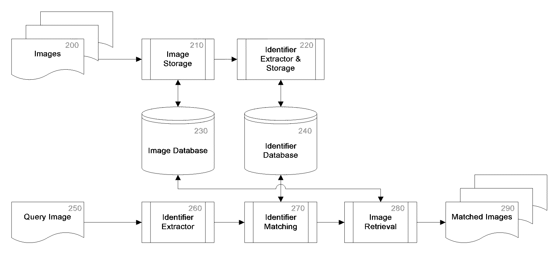
[0031]Various embodiments for deriving a representation of an image, specifically an image identifier, and for using such a representation / identifier for the purposes of, for example, identification, matching or validation of an image or images, will be described below. The present invention is especially useful for, but is not restricted to, identifying an image. In the described embodiments, an “image identifier” (also referred to simply as “identifier”, “signature” or “image signature”) is an example of a representation of an image and the term is used merely to denote a representation of an image, or descriptor.

[0032]The skilled person will appreciate that the specific design details of an image identification apparatus and method, according to an embodiment of the invention, and the derivation of an image identifier for use in image identification, is determined by the requirements related to the type of image modifications it should be robust to, the size of the identifier, ex...


PUM


Abstract

A method for deriving a representation of an image is described. The method involves processing signals corresponding to the image. At least one region of the image that is representative of the image is identified. In one embodiment, each identified region corresponds to a feature of the image. For each identified image region, a two dimensional function of at least part of the image region is derived and processed to obtain an intermediate representation of the at least part of the image region. A representation of the image is derived from the intermediate representation of at least one of the image regions.

Description

BACKGROUND TO THE INVENTION[0001]The present invention relates to a method and apparatus for representing an image, and, in addition, a method and apparatus for comparing or matching images, for example, for the purposes of searching or validation.DESCRIPTION OF THE RELATED ART[0002]The present invention relates to improvements upon the image identification techniques disclosed in earlier, co-pending European patent application No: EP 06255239.3, and UK patent application Nos: GB 0700468.2, GB 0712388.8 and GB 0719833.6, the contents of which are incorporated herein by reference. Details of the inventions and embodiments disclosed in these earlier, co-pending patent applications apply analogously to the present invention and embodiments.[0003]The image identification techniques used in the methods and apparatuses described in EP 06255239.3, GB 0700468.2, GB 0712388.8 and GB 0719833.6 each extract a short binary descriptor from an image (see FIG. 2). These techniques address many dra...

Claims


Application Information

Patent Timeline
Patent Type & Authority Patents(United States)
IPC IPC(8): G06K9/00G06V10/48
CPCG06F17/30247G06K9/6211G06K9/4633G06K9/4671G06F16/583G06V10/48G06V10/462G06V10/757
Inventor BOBER, MIROSLAWBRASNETT, PAUL
Owner RAKUTEN GRP INC
Why Eureka
Try Eureka