Multi-layer module

a fiber optic module and multi-layer technology, applied in the field of fiber optic modules, can solve the problems of insufficient slack storage of the splice module, difficulty in maintenance of the multi-fiber cable and/or splicing connection, and the disorganized optical cabl

Active Publication Date: 2014-02-25
CORNING OPTICAL COMM LLC
View PDF931 Cites 43 Cited by
  • Summary
  • Abstract
  • Description
  • Claims
  • Application Information

AI Technical Summary

Benefits of technology

[0009]Additional features and advantages will be set forth in the detailed description which follows, and in part will be readily apparent to those skilled in the art from that description or recognized by practicing the embodiments described herein, including the detailed description which follows, the claims, as well as the appended drawings.

Problems solved by technology

However, oftentimes, the fiber optic cable may become disorganized and / or tangled within the splice module, such that maintenance on the multi-fiber cable and / or splicing connection can become difficult.
Additionally, as maintenance is required, oftentimes a splice module is unable to store adequate slack to perform the desired maintenance.
Further, during installation and / or maintenance, a field technician may be uncertain whether the splice module will be utilized for single fiber splicing or mass fusion splicing until the field technician analyzes the cable configuration.
As current splice modules include a back entry opening for passing the multi-fiber cable to the splice module, access to the splice module may be difficult.
Additionally, such configurations may be difficult to install and / or maintain due to the field technician being unable to perform the desire procedures within the confined area of the telecommunications rack.

Method used


Image

  • Multi-layer module
  • Multi-layer module
  • Multi-layer module

Examples


Embodiment Construction

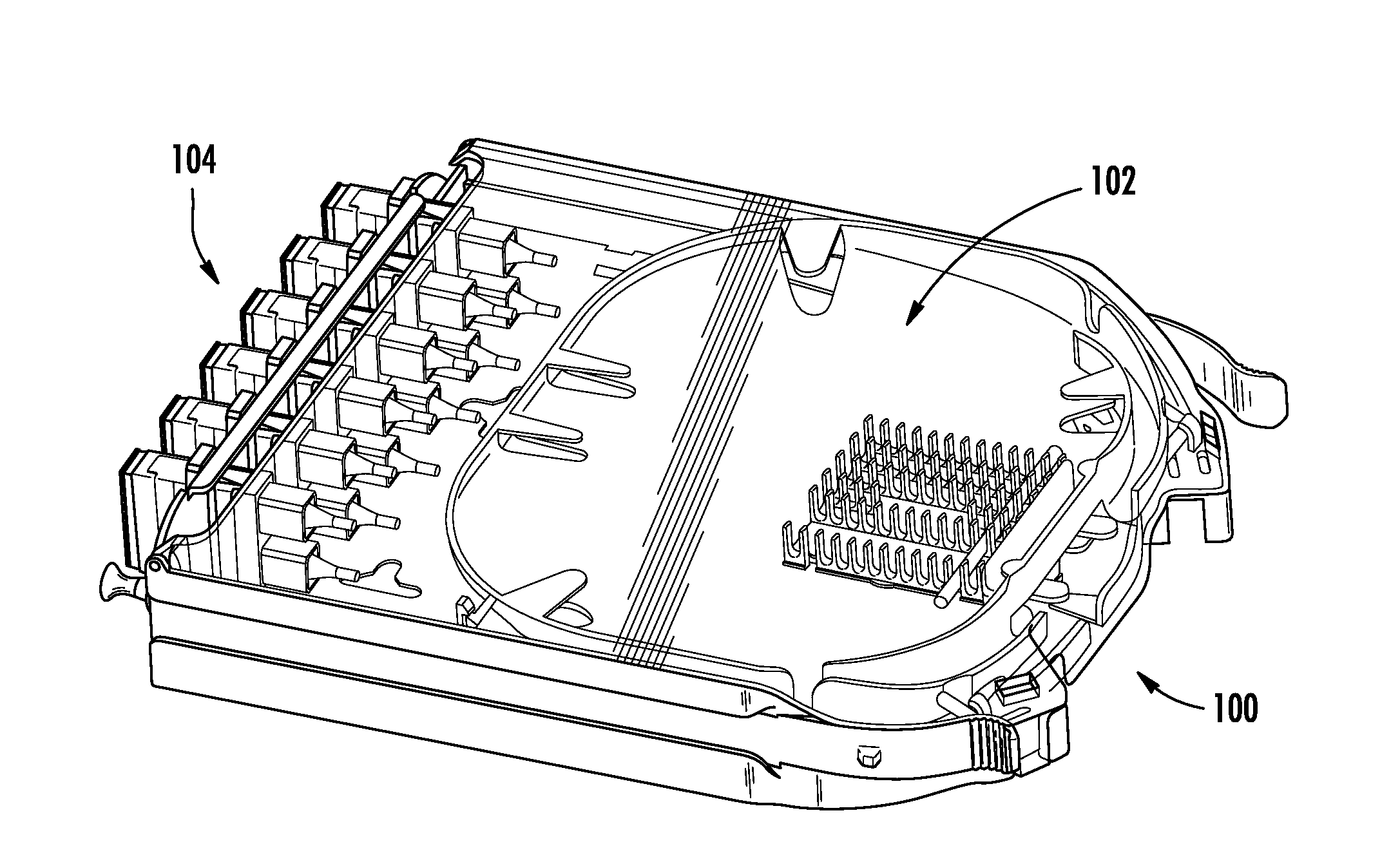
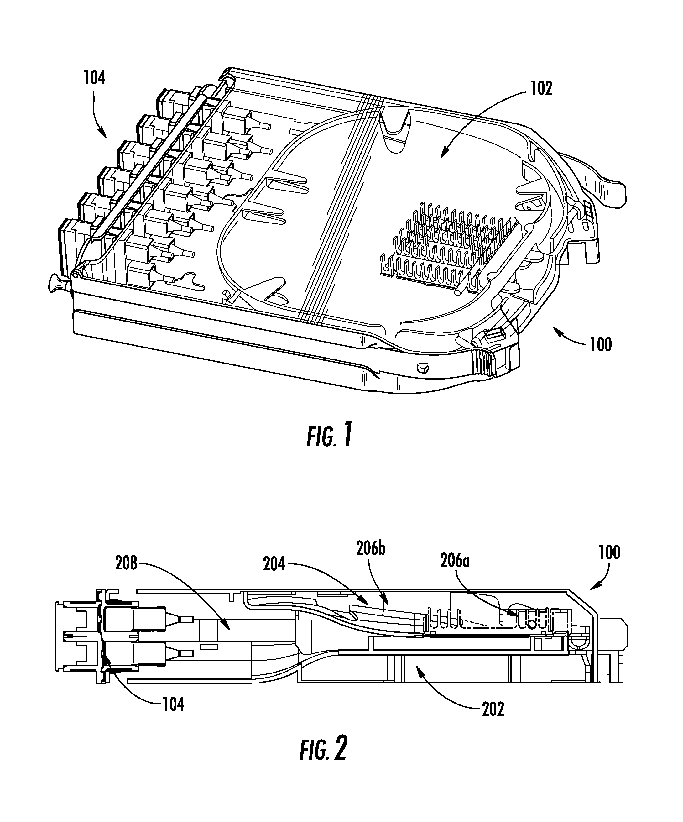
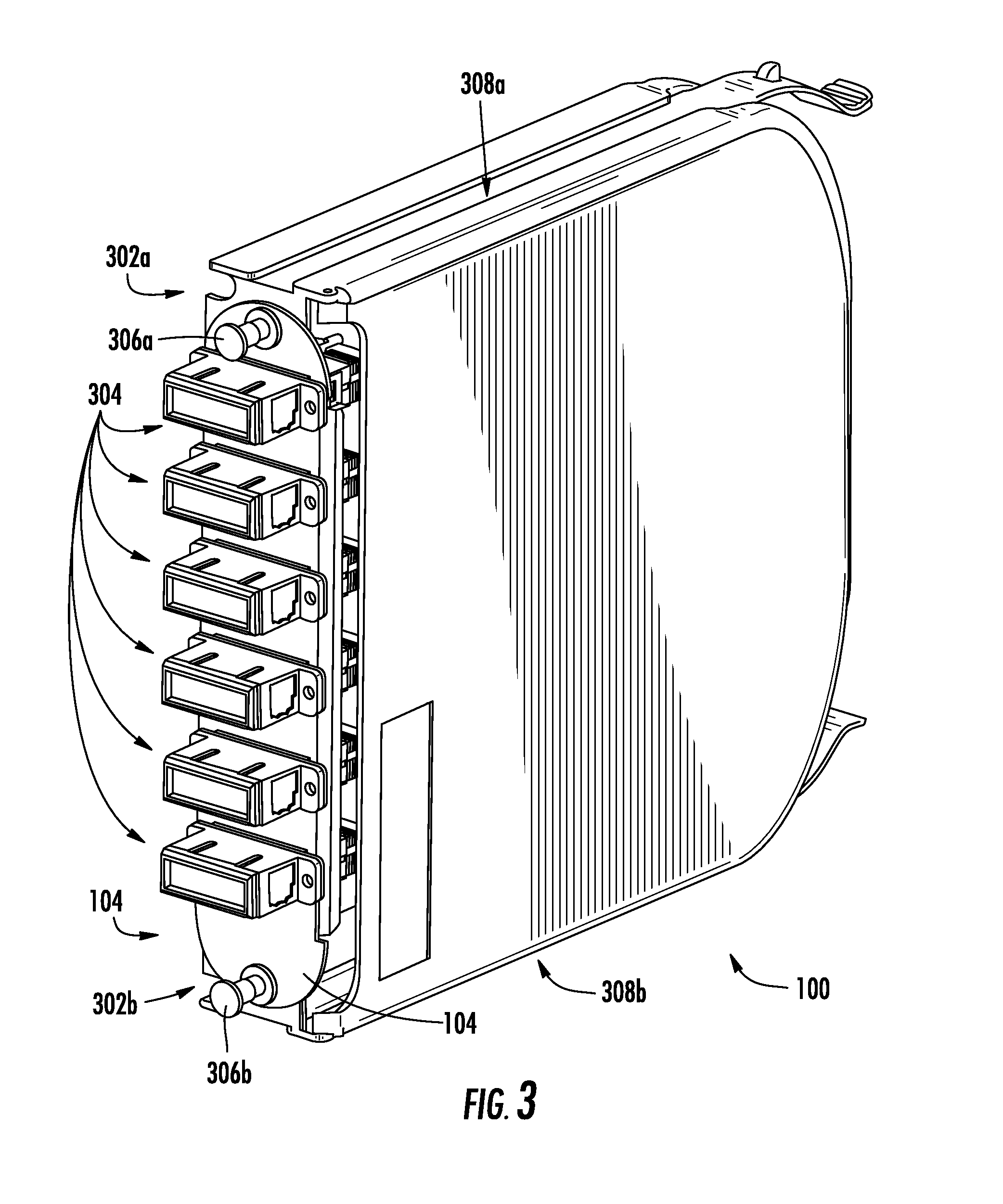
[0032]Referring initially to the drawings, FIG. 1 depicts a multi-layer module 100, according to embodiments disclosed herein. As illustrated, the multi-layer module 100 includes a housing that is coupled to a hinged cover 102 that is disposed on one of a pair of major faces and an adapter plate 104 that removably couples to the multi-layer module 100 at an adapter opening, where the adapter opening and the adapter plate collectively define an adapter plate area of the module housing. While the cover on the major face provides a closed framework, depending on the particular embodiment, the multi-layer splice module may have an open or closed framework. As illustrated, the hinged cover 102 may be substantially transparent such that a user may view inside the multi-layer module 100 without having to open the hinged cover 102. Additionally, the hinged cover 102 may provide an open position and / or a closed position. In the open position, the hinged cover 102 provides access to the splic...


PUM


Abstract

A multi-layer module that includes a multi-fiber cable storage layer having a cable entry opening and a cable winding structure is disclosed. Also included is a splice storage layer that is discrete from the multi-fiber cable storage layer, the splice storage layer having a splice layer receiving opening in communication with the multi-fiber cable storage layer and a slack storage area. The multi-layer module includes a pigtail storage layer that is discrete from both the multi-fiber cable storage layer and the splice storage layer, the pigtail storage layer having a pigtail connector area and a pigtail storage area, the pigtail storage area comprising a pigtail storage layer receiving opening in communication with the splice storage layer.

Description

CROSS REFERENCE[0001]This application claims priority to U.S. Provisional Ser. No. 61 / 330,162 filed on Apr. 30, 2010 and entitled “FIBER OPTIC MODULE”. This application is also related to U.S. application Ser. No. 12 / 956,446, entitled “Module with Adapter Side Entry Opening” and U.S. application Ser. No. 12 / 956,509, entitled “Multi-Configurable Splice Holder,” both of which were filed on the same day as this application and both of which are incorporated by reference in their entireties.BACKGROUND[0002]1. Field[0003]The present disclosure generally relates to fiber optic modules and, more specifically, to embodiments of a fiber optic module that utilize a plurality of layers for fiber management.[0004]2. Technical Background[0005]In fiber optic and other cable installations, there is often a desire to splice a field fiber in order to utilize a fiber adapter. As such, a multi-fiber cable may be routed to a splice module. The splice module may be configured to facilitate splicing of a...

Claims


Application Information

Patent Timeline
Patent Type & Authority Patents(United States)
IPC IPC(8): G02B6/46
CPCG02B6/4441G02B6/4454G02B6/4471G02B6/4453
Inventor GIRAUD, WILLIAM J.RASMUSSEN, MICHAEL H.RODRIGUEZ, DIANA
Owner CORNING OPTICAL COMM LLC
Why Eureka
Try Eureka