Method for computer-aided movement planning of a robot

a robot and computer-aided technology, applied in the field of robot computer-aided movement planning, can solve the problems of not being able to predict the surroundings of persons and/or operating personnel in the robotic system, and the straight movements in the configuration room in the stationary base coordinate system are often significantly curved, so as to shorten the computing time

Active Publication Date: 2014-02-25
SIEMENS HEALTHCARE GMBH
View PDF19 Cites 13 Cited by
  • Summary
  • Abstract
  • Description
  • Claims
  • Application Information

AI Technical Summary

Benefits of technology

[0006]The object underlying the invention is to create a method and a device for movement planning of a robot, which shortens the computing time needed for a collision-free movement trajectory of a robot.
[0017]In a particularly preferred variant of the invention, in the case of an ambiguous configuration occurring, that configuration is selected from the ambiguous configuration position, the distance of which from the configuration position of the spatial point previously lying on the trajectory being at its lowest. An erratic change between different configuration positions is avoided in this way.

Problems solved by technology

This is problematic in that straight movements in the configuration room in the stationary base coordinates system are often significantly curved particularly in the case of the articulated arm kinematics of the robotic system.
Furthermore, a curved movement in the stationary base coordinates system is not very plausible for persons and / or operating personnel in the surroundings of the robotic system and is thus rarely accepted.

Method used


Image

  • Method for computer-aided movement planning of a robot
  • Method for computer-aided movement planning of a robot
  • Method for computer-aided movement planning of a robot

Examples


Embodiment Construction

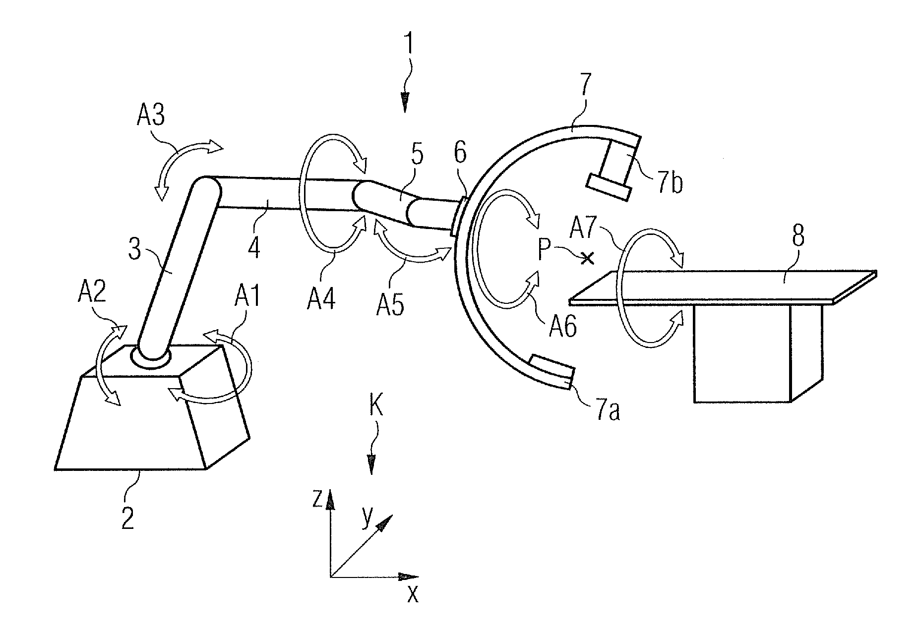
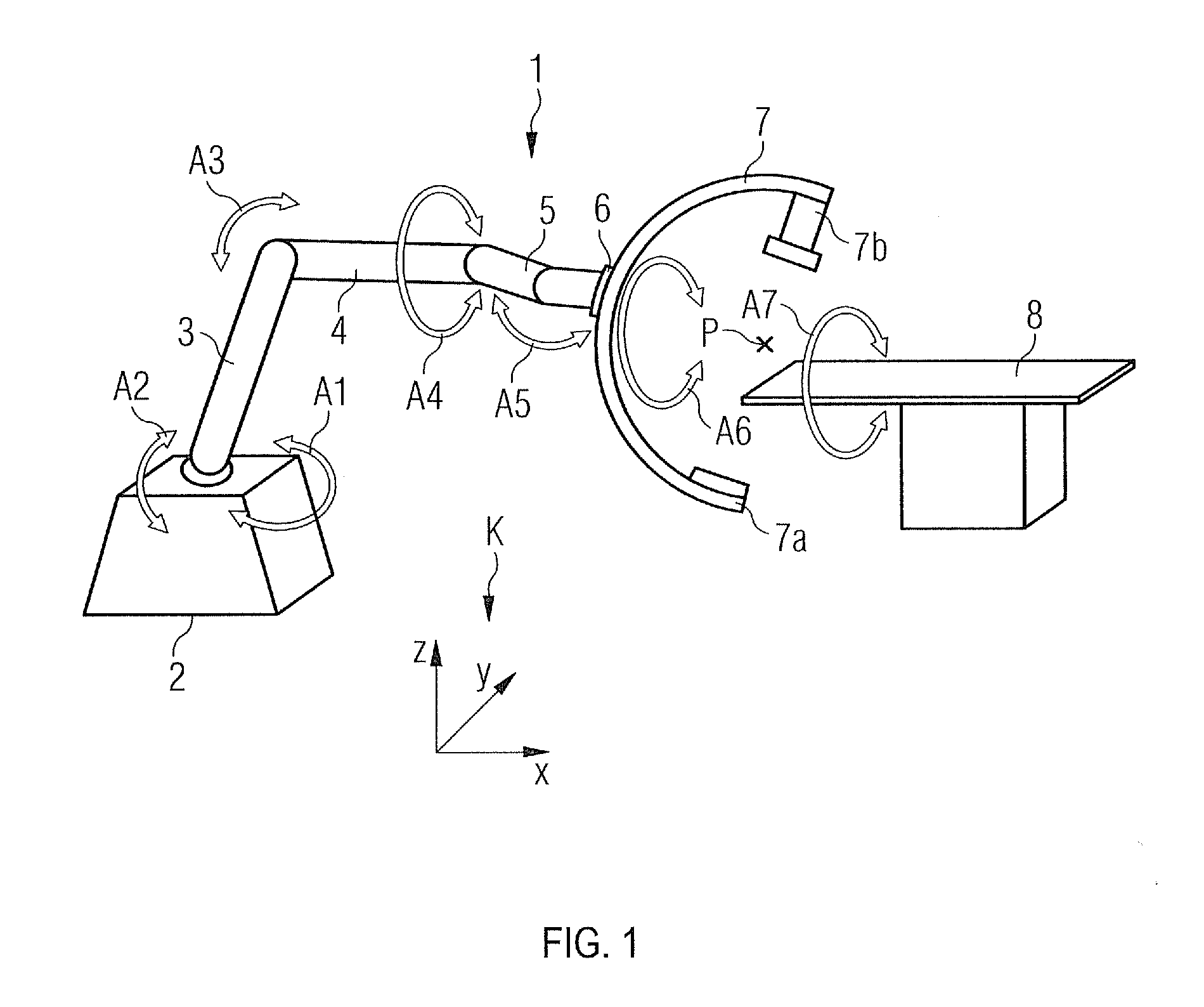
[0026]The robot-controlled x-ray device 1 shown in FIG. 1 includes a base frame 2, which can be fixedly mounted to the base of an operating theater for instance. A carousel (not shown in detail) is positioned on the base frame, said carousel enabling a movement of a system comprising arms and joints about a vertically moving axis A1. The system comprising arms and joints includes a rocker arm 3, which can be pivoted about a second axis of rotation A2. An arm 4 is fastened to the rocker arm 3 in a rotatable fashion about a third axis of rotation A3. A robotic hand 5 is attached to the end of the arm 4 so as to be rotatable about a fourth axis of rotation A4, said robotic hand having an interface 6 for coupling a so-called C-arm 7. The C-arm can be rotated here via the interface 6 about an axis of rotation A6 and can be pivoted about a fifth axis of rotation A5 which runs at right angles thereto.

[0027]The C-arm 7 includes an x-ray detector 7a on its front ends as well as a correspondi...


PUM


Abstract

A method for computer-aided movement planning of a robot is provided, in which a trajectory for the movement of a spatial point assigned to the robot is planned in a fixed coordinates system. The spatial positions are translated from a plurality of spatial positions of the spatial point into respective configuration positions in a configuration room of the robot based on inverse kinematics. The respective configuration positions are described by axial positions of one or several rotatory or translational movement axes of the robot and are tested for collisions and a trajectory is formed along spatial positions of the spatial point, the respective configuration positions of which are collision-free. Planning the movement in a fixed coordinates system improves the efficiency of the planning method and the planned movement corresponds more to the expectations of the persons or the operating staff in the surroundings of the robot.

Description

CROSS REFERENCE TO RELATED APPLICATIONS[0001]This application claims priority of German application No. 10 2008 021 386.1 filed Apr. 29, 2008 and German application No. 10 2008 057 142.3 filed Nov. 13, 2008, both of the applications are incorporated by reference herein in their entirety.FIELD OF THE INVENTION[0002]The invention relates to a method and a device for computer-aided movement planning of a robot.BACKGROUND OF THE INVENTION[0003]The movement planning of robotic systems aims at ensuring a collision-free movement of the robotic system between a corresponding start and target position. A collision-free movement trajectory along a plurality of intermediate positions is determined in this way using suitable planning methods, said intermediate positions being linked to one another by way of trajection elements.[0004]In known movement planning methods, the individual intermediate points and / or trajectory elements in the so-called configuration room are planned. The configuration...

Claims


Application Information

Patent Timeline
Patent Type & Authority Patents(United States)
IPC IPC(8): G06F19/00
CPCG05B2219/45117A61B6/4441G05B2219/40495B25J9/1664A61B6/4458
Inventor LURZ, WINFRIEDNEUBAUER, WERNERSCHONBORN, MANFRED
Owner SIEMENS HEALTHCARE GMBH
Why Eureka
Try Eureka