Editing system

a technology of editing system and general view, applied in the field of product design technology, can solve the problems of burdensome updating process, error, and technology not taking into account the early stages of product design

Active Publication Date: 2014-02-25
RICOH KK
View PDF7 Cites 1 Cited by
  • Summary
  • Abstract
  • Description
  • Claims
  • Application Information

AI Technical Summary

Benefits of technology

[0009]The present invention provides an editing system that substantially obviates one or more of the problems caused by the limitations and disadvantages of the related art.

Problems solved by technology

The process of updating the general view is not only burdensome but also leads to errors because the updating is performed manually.
Further, error also occurs due to the difficulty of visually confirming the connection specifications of the entire product.
However, this technology does not take into consideration the early stages of designing a product where specifications of the product are yet to be defined.
Therefore, the disclosed technology does not solve the above-described problems.

Method used


Image

  • Editing system
  • Editing system
  • Editing system

Examples


Embodiment Construction

[0034]Embodiments of the present invention are described with reference to the accompanying drawings.

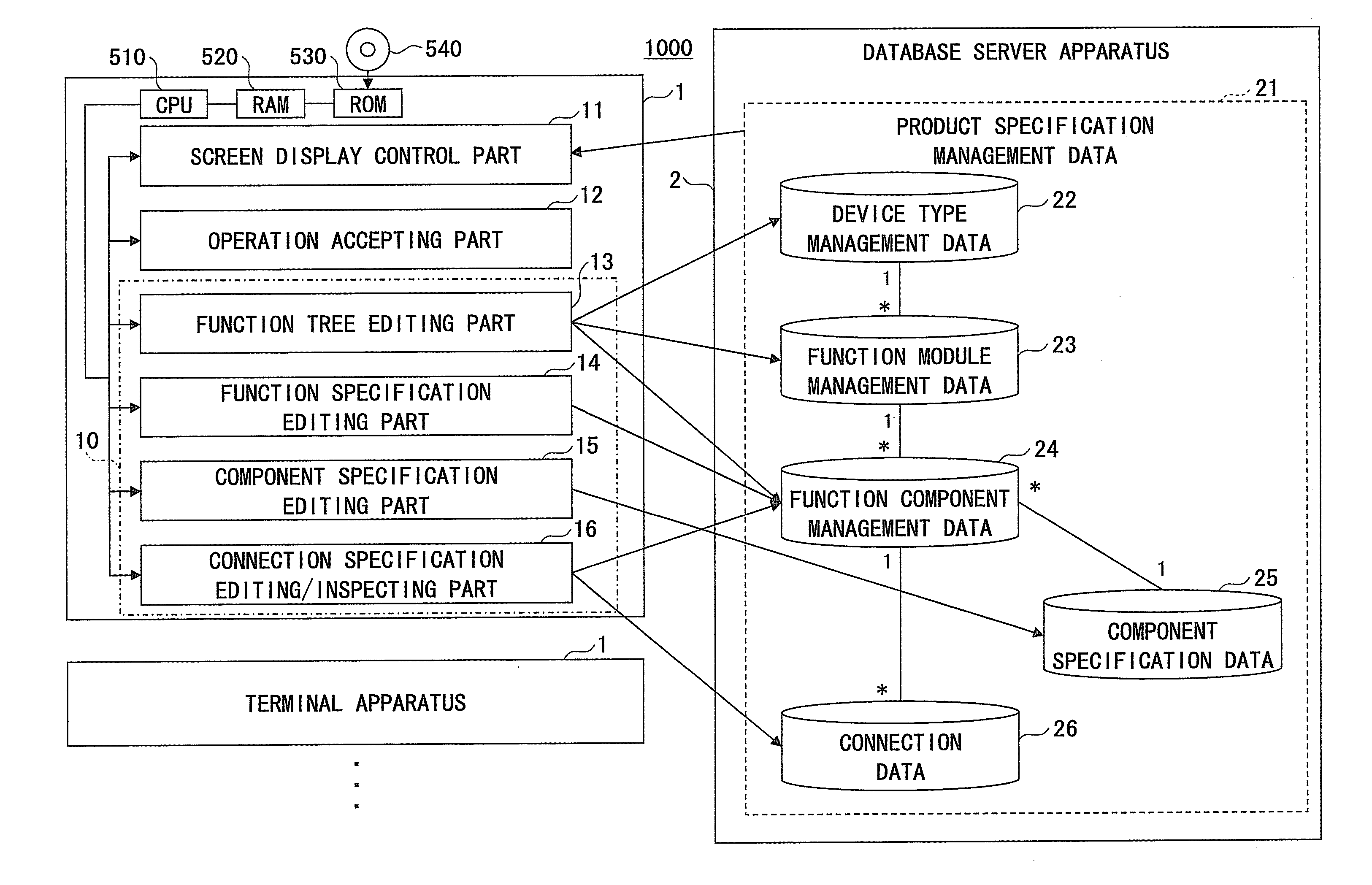
[0035]FIG. 2 is a schematic diagram illustrating a configuration of a system (editing system) 1000 for editing / inspecting an electric specification of an entire product according to an embodiment of the present invention.

[0036]In FIG. 2, the editing system 1000 includes one or more multiple terminal apparatuses 1 and a database server 2 that is connected to at least one of the multiple terminal apparatuses 1 via a network. The database server 2 does not need to be a single apparatus but also may be a combination of separate independent apparatuses.

[0037]The terminal apparatus (also referred to as “editing / inspecting apparatus”) 1 includes a screen display control part 11, an operation accepting part 12, a function tree editing part 13, a function specification editing part 14, a component specification editing part 15, and a connection specification editing / inspecting part 16. It is ...


PUM


Abstract

An editing system includes a database server apparatus having product specification management data stored therein; and a terminal apparatus including: a display part displaying a function tree and an IO table, the function tree hierarchically indicating elements along with attributes of each of the elements based on the product specification management data and having a product name as a root of the function tree, and the IO table indicating connection data between each pin of the elements based on the product specification management data, an accepting part accepting an operation to connect one element to another element, an operation to display connection data between the elements, and an operation to edit each item of the connection data of the IO table, and an updating part updating the connection data of the product specification management data in accordance with the operations accepted by the operation accepting part.

Description

CROSS-REFERENCE TO RELATED APPLICATIONS[0001]The present application is based on Japanese Priority Application No. 2012-024489 filed on Feb. 7, 2012, with the Japanese Patent Office, the entire contents of which are hereby incorporated by reference.BACKGROUND OF THE INVENTION[0002]1. Field of the Invention[0003]The present invention relates to technology for designing a product such as a MFP (Multi Function Printer, Multi Function Peripheral).[0004]2. Description of the Related Art[0005]At the early stages of designing a product such as an MFP, product specifications are undefined. Thus, in these stages, product design is conducted while referring to a diagram (general view) 300 illustrating mutual connections between the electrical components included in the product, and an IO (Input / Output) table illustrating the connection relationship with respect to each pin of the connectors of the electric components, and by manually updating the data indicated by the general view 300 and the...

Claims


Application Information

Patent Timeline
Patent Type & Authority Patents(United States)
IPC IPC(8): G06F17/50
CPCG06F17/5045G06F30/30
Inventor YOSHIMURA, TOSHIYA
Owner RICOH KK
Why Eureka
Try Eureka