Aerodynamic shroud for the back of a combustion chamber of a turbomachine

a turbomachine and combustion chamber technology, applied in the field of shrouds, can solve the problems of increasing the load loss of these airstreams, increasing the risk of airstream separation intended to bypass the combustion chamber and flow downstream along the radially internal wall, and not being able to achieve separation

Active Publication Date: 2014-03-04
SN DETUDE & DE CONSTR DE MOTEURS DAVIATION S N E C M A
View PDF25 Cites 7 Cited by
  • Summary
  • Abstract
  • Description
  • Claims
  • Application Information

AI Technical Summary

Benefits of technology

[0012]One aim of the invention is notably to provide a simple, economic and efficient solution to these problems, allowing at least some of the abovementioned disadvantages to be avoided.
[0015]Such an air intake scoop allows the air feed through the corresponding aperture of the shroud to be improved, notably by reducing the load loss incurred by the air traversing this aperture.
[0016]In addition, the bosses of the shroud enable guidance of the airstream flowing radially towards the interior and then downstream along the shroud to be improved, and in particular enable the risks of separation of this airstream to be reduced.
[0023]The shroud according to this second embodiment is particularly advantageous when it is used in a turbomachine in which the airstream originating from the compressor has a gyratory component in the direction from the protrusion of the extension of each aperture towards the axis of injection of the corresponding injector. This enables the scoop effect produced by these extensions with regard to the airstream originating from the compressor to be improved.
[0025]In this latter case, the inclination of the radially internal edge of the apertures relative to the tangential direction is advantageously such that this edge forms an acute angle with the direction of arrival of the airstream, where this angle is preferably a right angle. This enables the scoop effect produced by the extensions to be maximised.

Problems solved by technology

As a consequence, the airstream feeding the air inlet apertures of the injection devices and the airstream bypassing the combustion chamber along the radially internal wall of this chamber are subject to a substantial diversion radially towards the interior, which is such that it increases the load loss of these airstreams.
In addition, the applicant has observed that in these centrifugal compressor turbomachines there is an increased risk of separation of the airstream intended to bypass the combustion chamber and flow downstream along the radially internal wall of the combustion chamber, notably in order to feed the air inlet apertures of the chamber's coaxial walls, in proximity to the shroud and downstream from it in the radially internal region of the enclosure containing the combustion chamber.
And separations of this airstream are not desirable since they are likely to cause operational instabilities in the combustion chamber.

Method used


Image

  • Aerodynamic shroud for the back of a combustion chamber of a turbomachine
  • Aerodynamic shroud for the back of a combustion chamber of a turbomachine
  • Aerodynamic shroud for the back of a combustion chamber of a turbomachine

Examples


first embodiment

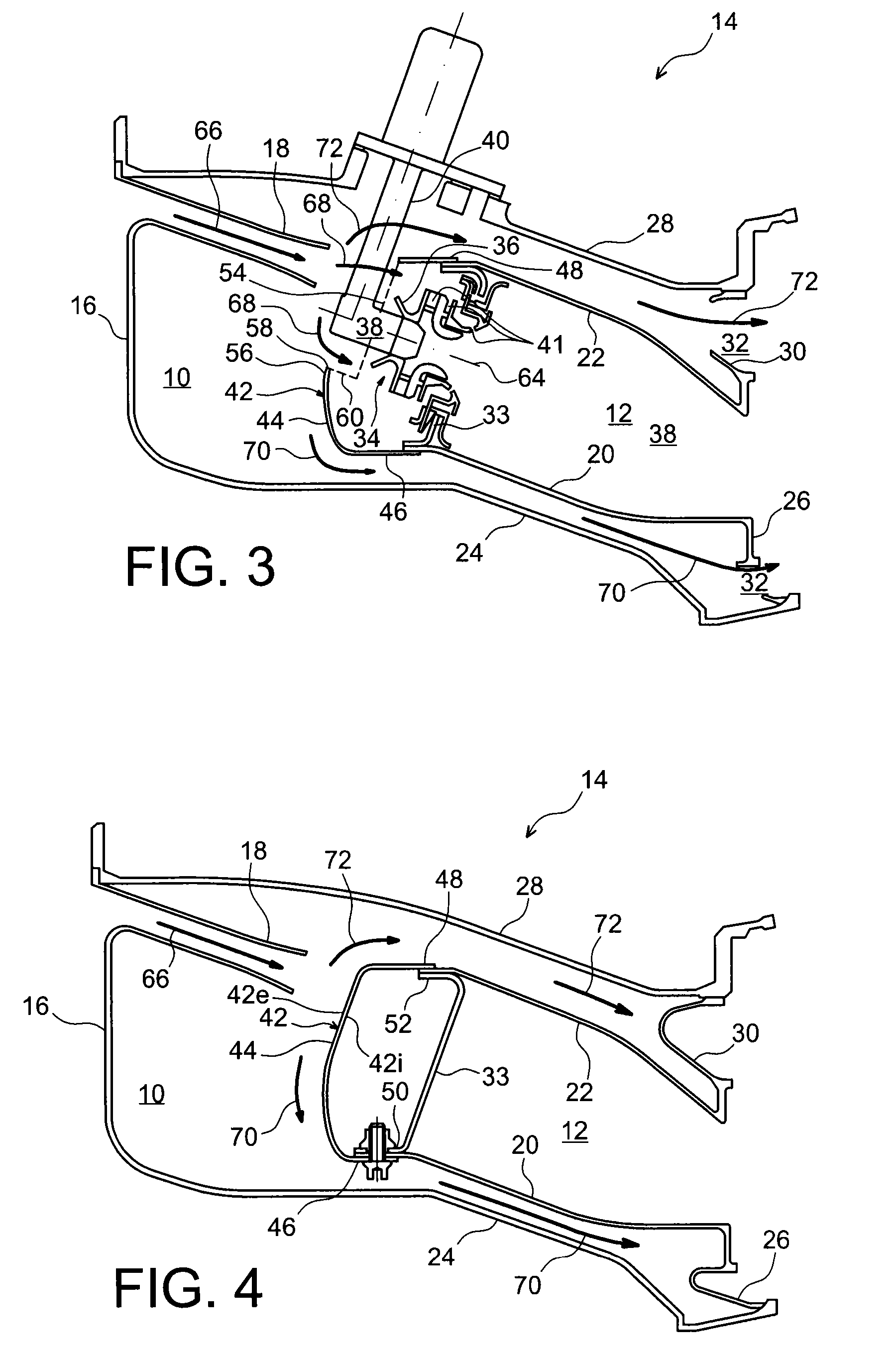
[0020]The shroud according to this first embodiment is particularly advantageous when it is used in a turbomachine in which the airstream originating from the compressor has no gyratory component.

second embodiment

[0021]In the invention the extension of each of the abovementioned apertures has a protrusion which is offset circumferentially relative to an axis of injection of the aperture.

[0022]Here again, the axis of injection of the aperture is the same as the axis of injection of an injector fitted in said aperture.

[0023]The shroud according to this second embodiment is particularly advantageous when it is used in a turbomachine in which the airstream originating from the compressor has a gyratory component in the direction from the protrusion of the extension of each aperture towards the axis of injection of the corresponding injector. This enables the scoop effect produced by these extensions with regard to the airstream originating from the compressor to be improved.

[0024]In addition, in this second embodiment of the invention, the radially internal edge of each aperture can be parallel to the tangential direction, or again inclined relative to this tangential direction.

[0025]In this lat...


PUM


Abstract

An annular shroud (42), having an internal face intended to cover the back end wall (33) of an annular combustion chamber (12) of a turbomachine (14) fitted with a centrifugal compressor, together with an external face opposite said internal face, and where said shroud includes multiple apertures (54) intended to allow fuel injectors (38, 40) supported by said back end wall (33) to pass through, together with multiple bosses (56) which extend as projections on said external face radially towards the interior respectively from the respective radially internal edges (58) of said apertures (54), such that each of said bosses (56) delimits an extension (60) of the corresponding aperture (54) open radially towards the exterior so as to form an air intake scoop.

Description

TECHNICAL FIELD[0001]The present invention relates to a shroud intended to cover the back end wall of an annular combustion chamber in a turbomachine, such as an aircraft turbomachine in particular.[0002]The invention also relates to a combustion chamber including a shroud of this type, together with a turbomachine including such a combustion chamber.[0003]The invention relates more particularly to a shroud intended to be fitted to the combustion chamber of a turbomachine including a compressor of the centrifugal type positioned upstream from the combustion chamber.STATE OF THE PRIOR ART[0004]A turbomachine annular combustion chamber is habitually housed in an annular enclosure downstream from a compressor of the turbomachine, and delimited by two coaxial walls, of essentially rotationally symmetrical cylindrical or tapered shape, where these walls are connected to one another roughly at their upstream ends by a back-of-chamber annular end wall fitted with air and fuel injection dev...

Claims


Application Information

Patent Timeline
Patent Type & Authority Patents(United States)
IPC IPC(8): F02C1/00
CPCF04D29/441F23R3/26F23R3/10F05D2250/52
Inventor BOURGOIS, SEBASTIEN ALAIN CHRISTOPHEHERNANDEZ, DIDIER HIPPOLYTE
Owner SN DETUDE & DE CONSTR DE MOTEURS DAVIATION S N E C M A
Why Eureka
Try Eureka