Pressure medium supply device of a hydraulically actuated shifting element

a technology of hydraulically actuated shifting element and supply device, which is applied in the direction of fluid actuated clutches, non-mechanical actuated clutches, clutches, etc., can solve the problems of affecting spontaneity in a negative manner, affecting the filling time of clutches and also the quality of shifting, and achieves simple and inexpensive methods. , the effect of improving the shift quality of the primary shift process

Inactive Publication Date: 2014-03-04
ZF FRIEDRICHSHAFEN AG
View PDF11 Cites 9 Cited by
  • Summary
  • Abstract
  • Description
  • Claims
  • Application Information

AI Technical Summary

Benefits of technology

[0008]The purpose of the present invention is to indicate a pressure medium supply device of a hydraulically actuated shifting element, with which draining of the pressure medium ducts when the internal combustion engine stops for a short time is avoided in a simple and inexpensive manner.
[0014]In an advantageous further development of the invention, the pressure-retaining valve is designed such that the shifting element is filled via an integrated filling orifice plate. In this case, to drain the shifting element the integrated filling orifice plate is bypassed, whereby the draining times are made shorter.
[0016]In a simple and inexpensive manner, the concept according to the invention prevents the pressure medium supply ducts of shifting elements from being able to drain when the internal combustion engine stops for a short time, and this considerably improves the shift quality of the primary shift process; for example, the pressure medium supply device described here can be used in vehicles with a start-stop function. Furthermore, it is ensured that the shifting element can still be drained and vented.

Problems solved by technology

With hydraulically actuated shifting elements the problem arises that if the internal combustion engine is stopped even for only a short time, the clutch supply ducts are drained, which has the disadvantageous result that when the vehicle is restarted, these ducts first have to be filled again.
This means that due to the additional time required for filling the clutch supply ducts, spontaneity is affected in a negative manner.
In addition, the air present in the cutch supply ducts must be expelled from the ducts and this has a negative effect on the clutch filling times and also on the quality of shifting.
Disadvantageously, the design known from DE 102 305 01 A1 is relatively complicated and involves high manufacturing, assembly and maintenance costs.

Method used


Image

  • Pressure medium supply device of a hydraulically actuated shifting element
  • Pressure medium supply device of a hydraulically actuated shifting element
  • Pressure medium supply device of a hydraulically actuated shifting element

Examples


Embodiment Construction

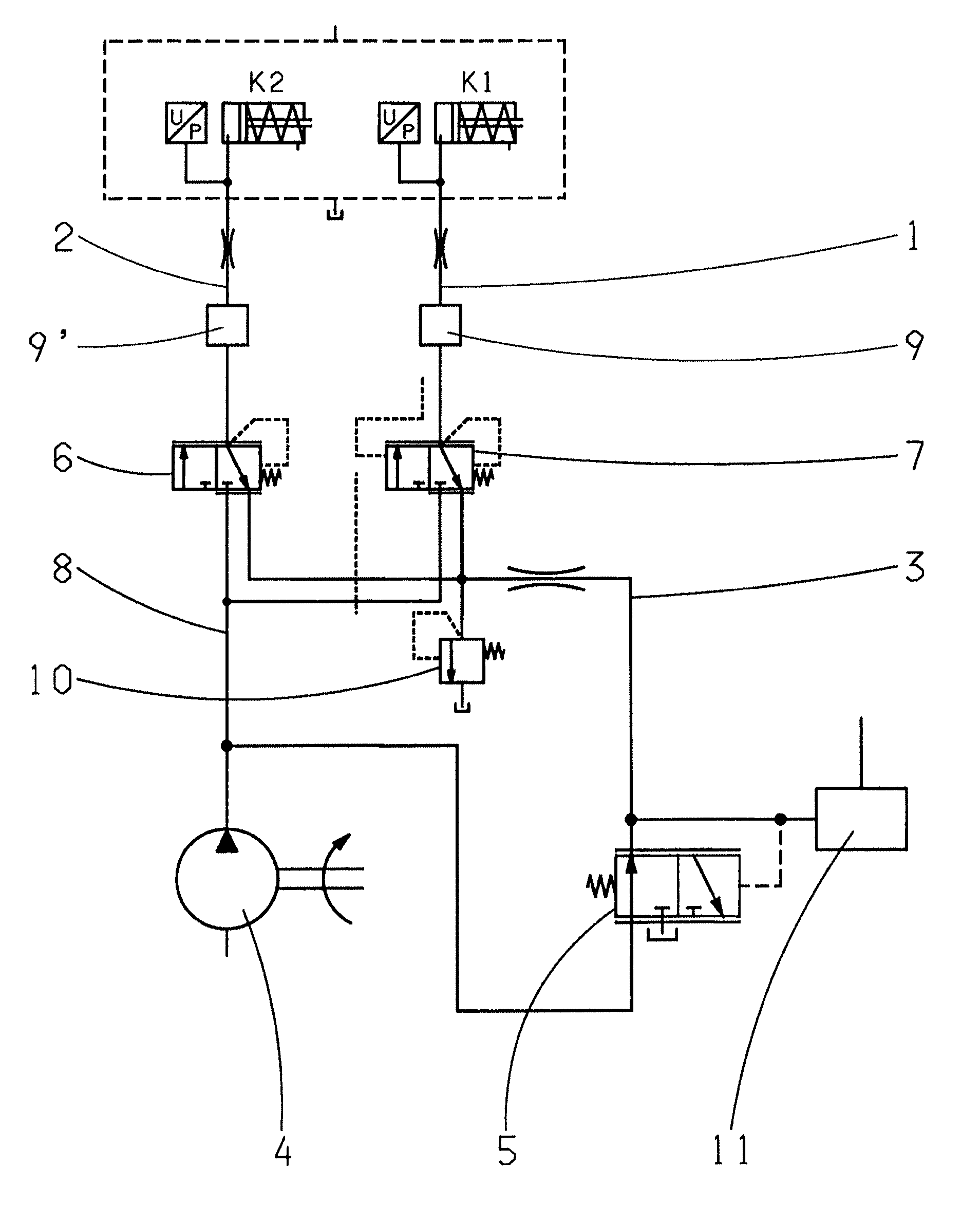
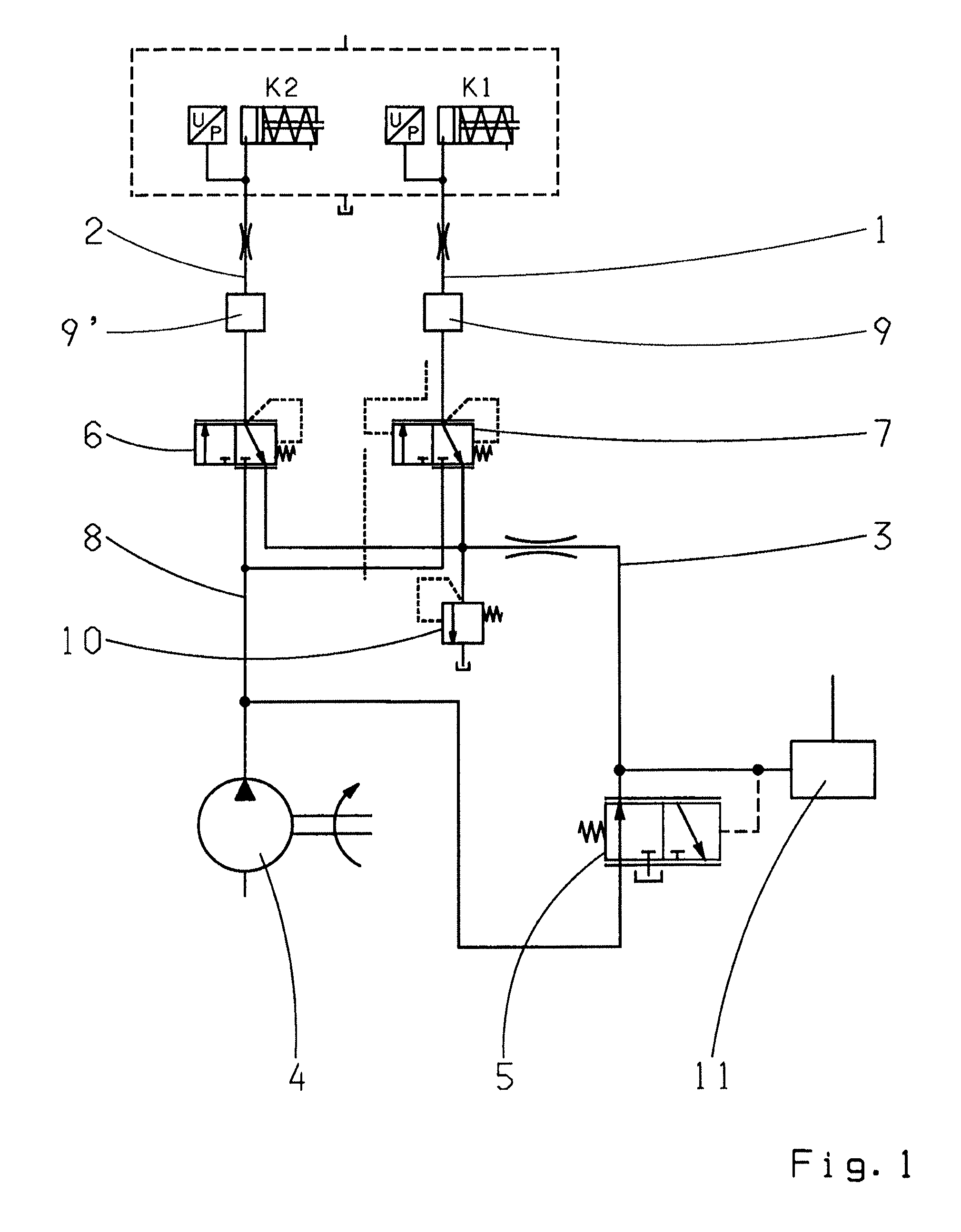
[0021]According to the invention, and referring to FIG. 1, the pressure medium supply device of a hydraulically actuated dual clutch comprises two pressure medium supply ducts 1, 2, each respectively associated with one clutch K1, K2 of the dual clutch and each comprising a respective clutch valve 6, 7. In addition a common line 3 for pre-filling the two clutches K1, K2 is provided, which is fluidically connected on the one hand to a pressure-limiting valve 5 arranged downstream from the pump 4 and on the other hand to the two pressure medium supply ducts 1, 2. The pressure medium supply ducts 1, 2 are connected to the pump 4 by a further line 8. In the attached figure a valve for setting the pre-filling pressure is indexed 10 and the pressure regulator is indexed 11.

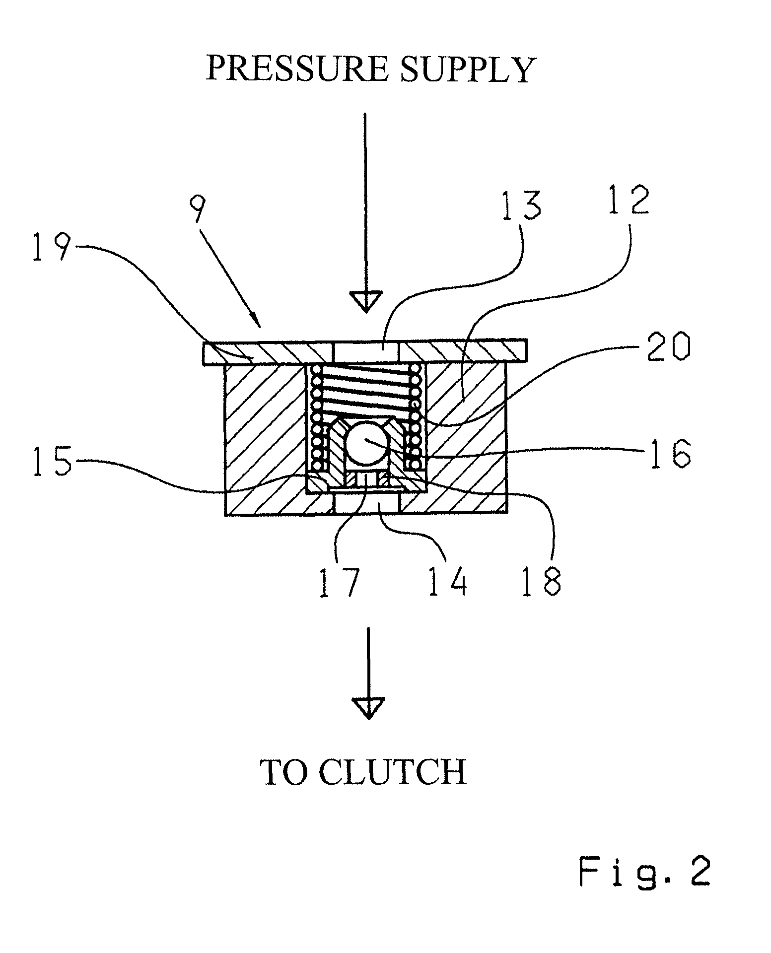
[0022]According to the invention, in each of the pressure medium supply ducts 1, 2 an additional pressure-retaining valve 9, 9′ or a check diaphragm is integrated between the shifting element K1, K2 and the respective s...


PUM


Abstract

A pressure medium supply device of a hydraulically actuated shifting element (K1, K2) comprises at least one pressure medium supply duct (1, 2) in communication with a pump (4) and a line (3) for pre-filling of the shifting element. An additional pressure-retaining valve (9, 9′) or a check diaphragm is integrated in the pressure medium supply duct (1, 2), between the shifting element and the shifting element valve (6, 7), and can be closed in the draining direction of the pressure medium supply duct (1, 2). The pressure-retaining valve (9, 9′) is designed such that the shifting element can be drained and the pressure medium supply device can be vented.

Description

[0001]This application is a National Stage completion of PCT / EP2010 / 057595 filed Jun. 1, 2010, which claims priority from German patent application serial no. 10 2009 027 097.3 filed Jun. 23, 2009.FIELD OF THE INVENTION[0002]The invention concerns a pressure medium supply device of a hydraulically actuated shifting element.BACKGROUND OF THE INVENTION[0003]With hydraulically actuated shifting elements the problem arises that if the internal combustion engine is stopped even for only a short time, the clutch supply ducts are drained, which has the disadvantageous result that when the vehicle is restarted, these ducts first have to be filled again. This means that due to the additional time required for filling the clutch supply ducts, spontaneity is affected in a negative manner. In addition, the air present in the cutch supply ducts must be expelled from the ducts and this has a negative effect on the clutch filling times and also on the quality of shifting.[0004]DE 102 305 01 A1 des...

Claims


Application Information

Patent Timeline
Patent Type & Authority Patents(United States)
IPC IPC(8): F16D25/10F16D25/12
CPCF16D2048/0221F16D48/0206F16D25/14
Inventor MARTIN, HANS-JOACHIMFRITZER, ANTON
Owner ZF FRIEDRICHSHAFEN AG
Why Eureka
Try Eureka