Light output device and control method

a technology of light output device and control method, which is applied in the direction of lighting and heating apparatus, semiconductor devices for light sources, instruments, etc., can solve the problems of limiting the versatility and applicability of light output devi

Active Publication Date: 2014-03-04
KONINK PHILIPS ELECTRONICS NV
View PDF8 Cites 2 Cited by
  • Summary
  • Abstract
  • Description
  • Claims
  • Application Information

AI Technical Summary

Benefits of technology

[0009]Thus, the invention is based on the understanding that switchable liquid crystal-based devices can be used to dynamically manipulate the output beam shapes of light emitted from light source units embedded in laminated glass. The manipulation, e.g. more or less collimation, may be achieved without mechanical movements. One switchable liquid crystal-based device may be provided for each light source unit for refined control of the overall beam shape, and the switchable liquid crystal-based devices are preferably arranged in front of the light source units. Further, the switchable liquid crystal-based devices may be relatively thin, making them suitable for use in the likewise thin laminated glass structure.
[0010]Preferably, the switchable liquid crystal-based devices are selectively or individually addressable, that is, they can be controlled independently so that any number of the liquid crystal-based devices can be switched at a given moment. For instance, the light originating from some light source units may be flooded (wide), while the light emitted by other light source units may be more collimated. This provides for a versatile and applicable light output device. For example, different objects lighted up by the light output device may be illuminated with different beam shapes, to emphasize a certain object or objects. In another example, where the light output device comprises light source units of different colors, a certain color may be flooded (voltage to the corresponding liquid crystal-based devices switched on), while another color is more collimated (voltage to the corresponding liquid crystal-based devices switched off), to create various lighting effects. Alternatively, all switchable liquid crystal-based devices may be addressed jointly, to provide a unified lighting effect.
[0011]Returning to WO2005121641, the switchable liquid crystal-based device disclosed therein comprises a first (bottom) transparent element having a fixed refraction index and a second, superimposed transparent element having an electrically adaptable refractive index, the second element comprising a liquid crystal layer. By electrically changing the refractive index of the second element, the difference in refraction index of the first and second elements is changed, which in turn influences the angular distribution of light propagating from the first to the second element. Hereto, in an advantageous embodiment of the light output device of the present invention, where the light source units are arranged between a top glass plate and a bottom glass plate of the laminated glass structure, the above first bottom transparent element of the switchable liquid crystal-based devices is formed by said top glass plate. Thus, the switchable liquid crystal-based devices are “partly integrated” with the top glass plate and no dedicated elements having the fixed refractive index are necessary, which may reduce cost and make manufacturing of the light output device more efficient. Alternatively, the switchable liquid crystal-based devices including any fixed refractive index element may be placed outside the laminated glass structure, on top of the top glass plate and aligned with the corresponding light source units. This provides for easy mounting of the switchable liquid crystal-based devices. As yet other alternatives, the liquid crystal-based devices including the elements having the fixed refractive index may be integrated into the top glass plate or placed beneath the top glass plate. The latter two alternatives allow a smooth top surface of the light output device to be maintained.

Problems solved by technology

However, a problem in such devices is that the output beam shapes are static, that is, the light emitted from the LEDs of the device have a predetermined collimation or dispersion, limiting the versatility and applicability of the light output device.

Method used


Image

  • Light output device and control method
  • Light output device and control method
  • Light output device and control method

Examples


Embodiment Construction

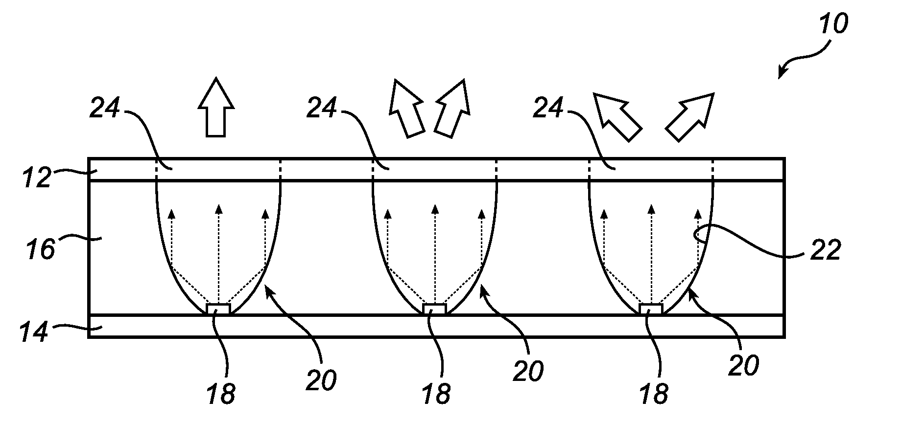
[0020]FIG. 1 is a schematic, cross-sectional side view of a light output device 10 according to an embodiment of the present invention.

[0021]The light output device 10 comprises a top glass plate (cover plate) 12 and a bottom glass plate 14. The glass could be transparent or translucent. Between the glass plates 12, 14, an intermediate layer 16 is provided, for instance polyvinylbutyral (PVB). During manufacturing, the two glass plates 12, 14 are bonded with the PVB layer 16 under heat and pressure to create a single laminated glass structure.

[0022]In the intermediate layer 16, a plurality of LED units 18 adapted to emit light are arranged side by side at the bottom glass plate. In order to power and control the LED units 18, suitable electrical connections are provided (not shown). Each LED unit 18 may comprise a single LED (e.g. white or monochromatic) or several LEDs (e.g. one red, one green, and one blue LED, or red-green-blue-amber). The latter creates a mixed light. Also, the ...


PUM

PropertyMeasurementUnit
voltagesaaaaaaaaaa
sizeaaaaaaaaaa
sizeaaaaaaaaaa

Abstract

The present invention relates to a light output device (10) comprising a plurality of light source units (18) arranged in a laminated glass structure. The light output device is characterized by a plurality of switchable liquid crystal-based (24) devices arranged to alter the beam shapes of light emitted by the light source units when in a beam shape altering mode. The present invention also relates to a method for controlling a light output device.

Description

FIELD OF THE INVENTION[0001]The present invention relates to a light output device comprising a plurality of light source units arranged in laminated glass. The present invention also relates to a method for controlling a light output device.BACKGROUND OF THE INVENTION[0002]Laminated glass is typically manufactured by permanently bonding two or more lites or plates of glass with an interlayer, for instance polyvinylburtyal (PVB), under heat and pressure, to create a single structure.[0003]Laminated glass can be used in a variety of applications. It can for instance be used in light output devices, wherein light emitting diodes (LEDs) are embedded in the laminated glass structure.[0004]However, a problem in such devices is that the output beam shapes are static, that is, the light emitted from the LEDs of the device have a predetermined collimation or dispersion, limiting the versatility and applicability of the light output device.SUMMARY OF THE INVENTION[0005]It is an object of the...

Claims


Application Information

Patent Timeline
Patent Type & Authority Patents(United States)
IPC IPC(8): G02F1/1335F21V9/40
CPCB32B17/10036F21S10/02F21V14/003B32B17/10761B32B17/10541F21Y2101/02F21Y2115/10
Inventor WANG, LINGLIDE BOER, DIRK KORNELIS GERHARDUS
Owner KONINK PHILIPS ELECTRONICS NV
Why Eureka
Try Eureka