High speed digital transient waveform detection system and method for use in an intelligent electronic device
a detection system and high-speed technology, applied in the measurement of pulse characteristics, noise figures or signal-to-noise ratio measurements, instruments, etc., can solve the problems of severe compromise of power quality monitoring capabilities of ieds, achieve faster and more sensitive measurement of transients, avoid introduction of crosstalk, and better analyze detected transients
- Summary
- Abstract
- Description
- Claims
- Application Information
AI Technical Summary
Benefits of technology
Problems solved by technology
Method used
Image
Examples
first example
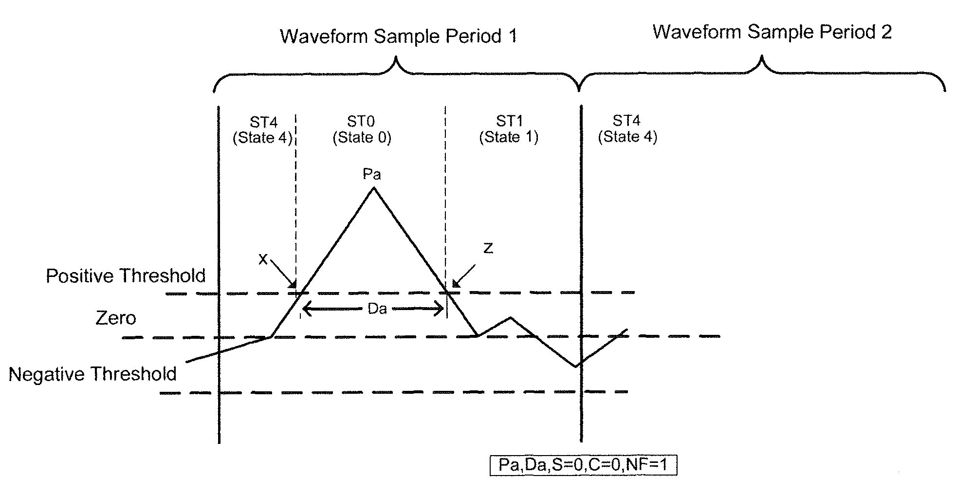
I. First Example
[0144]FIG. 6 (a) shows a first example of a transient waveform sample, discussed in the context of the various states of the state diagram of state machine 206, as illustrated in FIG. 5. As shown in FIG. 6(a), the transient waveform at the initial (left hand) boundary of waveform sample period 1, is shown to be below the positive voltage threshold level for at least one previous waveform sample period, and above the negative voltage threshold level, causing the state machine to start out in state 4. Recall from above that reflects State (4) corresponds to a state where the transient is determined to be below the positive threshold and at a waveform sample boundary. The transient waveform is then shown to rise until it is crosses the positive threshold at point “x”. At this point the threshold comparator CMP (B) 204 output is true causing the state machine 206 to transition from state (4) to state (0). Recall that state (0) corresponds to a state where a transient is ...
second example
II. Second Example
[0150]FIG. 6 (b) illustrates a second non-limiting illustrative example of how the transient waveform detection system operates on an exemplary transient waveform. In the present illustrative example, there are shown three peak values having magnitudes of Pa, Pb, and Pc, respectively. Each peak value has a respective associated duration of Da, Db and Dc.
[0151]With continued reference to FIG. 6(b), the first transient initially rises above 0 volts in waveform sample period 1 and continues to rise but remains below the positive threshold level as it drops slightly. Since this spike is below the positive threshold and above the negative threshold, the state machine 206 recognizes that this is not a peak transient and consequently enters into State (4) at the left boundary of waveform sample period 1, indicating that the transient is below the positive threshold.
[0152]The transient then rises above the positive threshold at point “x1” to eventually reach a peak value o...
third example
III. Third Example
[0158]FIG. 6(c) illustrates an example of when a transient continues over multiple waveform sample periods (i.e., waveform sample periods 1 and 2) and how the state machine 206 is able to recognize and store this information.
[0159]In FIG. 6(c), the transient is initially shown to be below the positive threshold. The state machine 206 enters into State (4) whenever this occurs. The transient then rises above the positive threshold with the state machine 206 entering State (0) and reaching its peak value Pa at the end of the waveform sample period 1. The duration for transient Pa is shown to be Da. The latch values 222, 224, 226, 228, 230 of the transient detect controller 114 at the end of waveform sample period 1 are: peak transient=Pa, peak transient duration=Da, S=0, C=1 and NF=1. Latch value C=1 because the transient persists across the waveform sample period boundary from period 1 to 2 and remains above the positive threshold.
[0160]At the beginning of waveform ...
PUM
 Abstract
Description
Claims
Application Information
 - R&D
- Intellectual Property
- Life Sciences
- Materials
- Tech Scout
- Unparalleled Data Quality
- Higher Quality Content
- 60% Fewer Hallucinations
Browse by: Latest US Patents, China's latest patents, Technical Efficacy Thesaurus, Application Domain, Technology Topic, Popular Technical Reports.
© 2025 PatSnap. All rights reserved.Legal|Privacy policy|Modern Slavery Act Transparency Statement|Sitemap|About US| Contact US: help@patsnap.com


