Shielding electronic components from liquid

a technology of electronic components and liquid, which is applied in the direction of electrical apparatus casings/cabinets/drawers, ventilation systems, heating types, etc., can solve the problems that fuel dispensers that may be covered by an awning or other form of cover may still be exposed to environmental conditions, and achieve the effect of reducing momentum and facilitating removal from airflow

Inactive Publication Date: 2014-03-11
WAYNE FUELING SYST
View PDF17 Cites 5 Cited by
  • Summary
  • Abstract
  • Description
  • Claims
  • Application Information

AI Technical Summary

Benefits of technology

[0008]Various implementations of a component shielding device may include one or more of the following features. For example, a component shielding device may at least partially prevent liquid (e.g., water) from entering a fuel dispenser component, such as, for instance, a currency acceptor. As another example, a component shielding device may help prevent an unauthorized access into a fuel dispenser component by a foreign object, such as a fuel dispenser customer's hand. As yet another example, a component shielding device may slow the momentum of an airflow pulled into the fuel dispenser used to cool and / or heat one or more components of the fuel dispenser in order to, for instance, allow liquid to be more easily removed from the airflow. As yet another example, a component shielding device may assist a gravitational effect in removing particulate matter entrained in the airflow.

Problems solved by technology

Moreover, fuel dispensers that may be covered by an awning or other form of cover may still be exposed to environmental conditions, such as, for example, sunlight, heat, snow, rain, hail, or fog.
In addition to retail fueling locations that include fuel dispensers in an outdoor environment, some fueling locations may locate fuel dispensers in an indoor environment, yet exposed to various hazards, such as water, chemicals, or other intrusive substances.

Method used


Image

  • Shielding electronic components from liquid
  • Shielding electronic components from liquid
  • Shielding electronic components from liquid

Examples


Embodiment Construction

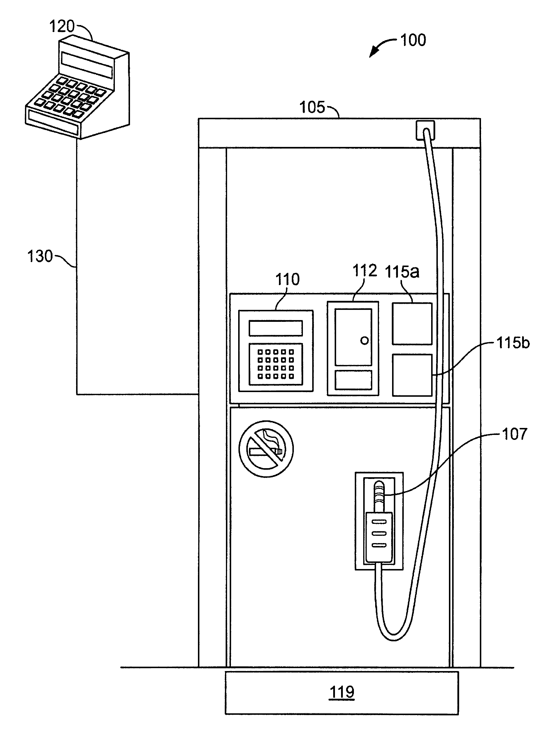
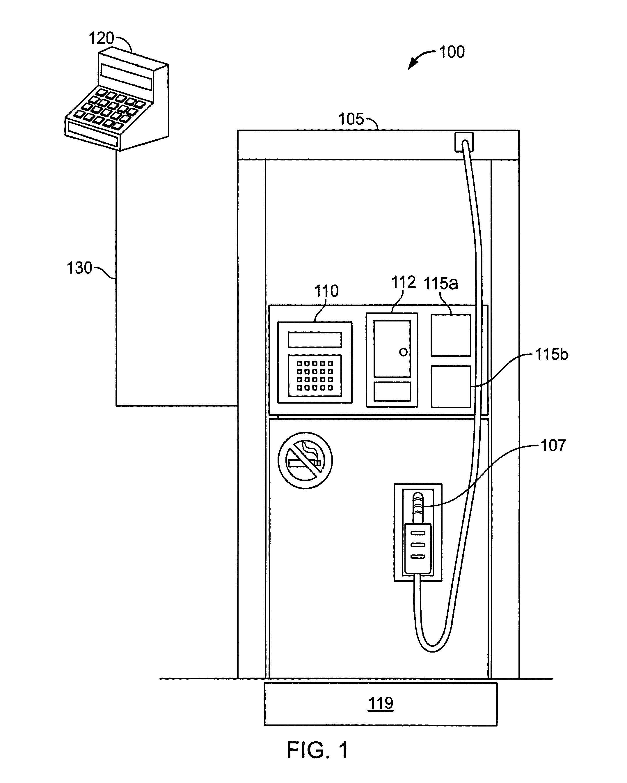
[0017]Liquid intrusion prevention may be a concern in many industries in which electronic or electrical components or systems are placed and used in outdoor environments. In particular, the retail fuel dispensing industry may be one such industry where concern is generated due to the placement and use of electric or electronic components, such as fuel dispensers, in outdoor environments. Certain components of a fuel dispenser, such as, for instance, a currency acceptor, a payment module, a liquid crystal display (LCD), and an electronic “head” (i.e., an embedded computer that may control, among other aspects, a pumping mechanism of the fuel dispenser), may function best in a substantially dry environment. These components, however, may also generate heat as they operate in the fuel dispenser. In some cases, beat dissipation may be desired in order for the fuel dispenser component (e.g., the currency acceptor) to remain functional and achieve its desired operating life. A system for ...


PUM


Abstract

Shielding liquid from electronic components may be accomplished by a variety of systems, devices, and techniques. A shielding may include a substantially vertical channel mounted to a fuel dispenser component; an airflow inlet; a plurality of arrays of angled protrusions; and a plurality of substantially vertical protrusions. The channel is adapted to guide an airflow. The plurality of arrays of angled protrusions are, disposed within the channel and are substantially parallel in arrangement within each array. The angled protrusions within each array are angularly offset in arrangement relative to the angled protrusions within adjacent arrays. The arrays of angled protrusions are adapted to form a tortuous path for the airflow through the channel. The plurality of substantially vertical protrusions are disposed within the channel and are located between the airflow inlet and the plurality of arrays. The vertical protrusions are adapted to substantially straighten the airflow within the channel.

Description

TECHNICAL BACKGROUND[0001]This disclosure relates to shielding electronic components from liquid, and more particularly, to systems and techniques for shielding fuel dispenser components from liquid.BACKGROUND[0002]The retail petroleum industry utilizes fuel dispensing equipment in a variety of environments and locations. In some instances, a retail fueling location may include one or more fuel dispensers located in an outdoor environment. Although the outdoor environment may include a form of cover above the fuel dispenser, other retail fueling locations may include fuel dispensers in an uncovered environment. Moreover, fuel dispensers that may be covered by an awning or other form of cover may still be exposed to environmental conditions, such as, for example, sunlight, heat, snow, rain, hail, or fog. In addition to retail fueling locations that include fuel dispensers in an outdoor environment, some fueling locations may locate fuel dispensers in an indoor environment, yet expose...

Claims


Application Information

Patent Timeline
Patent Type & Authority Patents(United States)
IPC IPC(8): H02K7/20H05K5/00H05K7/20F24F7/007
CPCB67D7/84
Inventor ZUZEK, PATRICKJOHNSON, MARK JUSTIN
Owner WAYNE FUELING SYST
Why Eureka
Try Eureka