

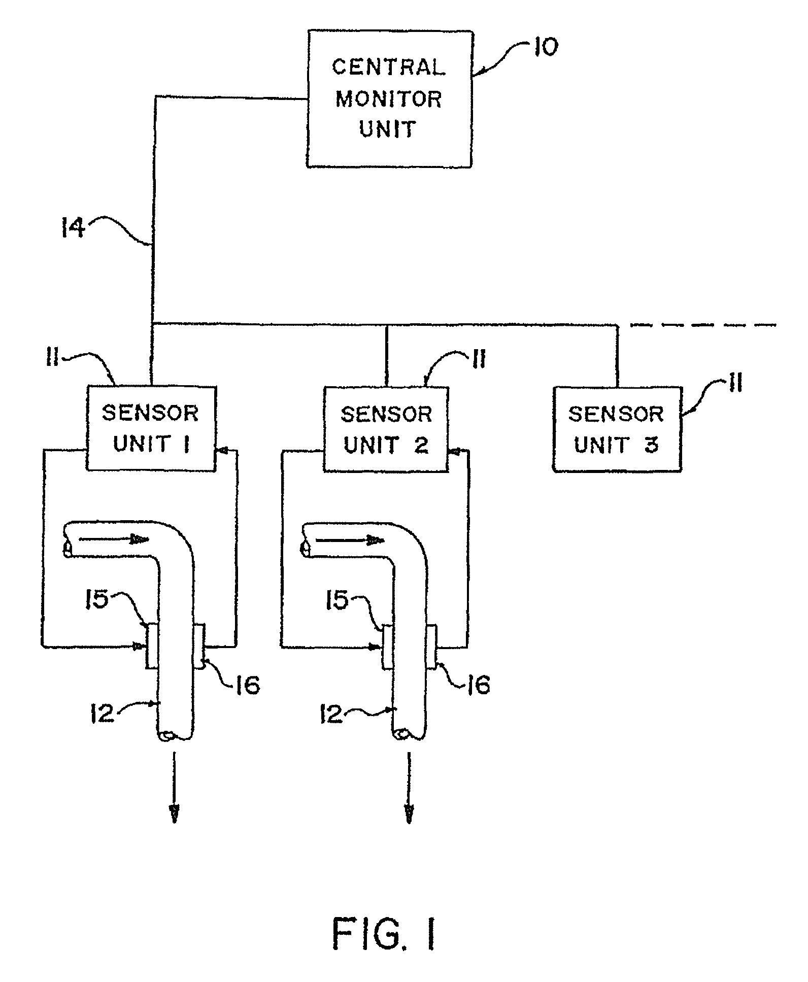
Arrangement of sensors in a seed counting apparatus for a planter monitor
a technology of planter monitor and counting apparatus, which is applied in the direction of application, sowing, instruments, etc., can solve the problems of false counting, dust arising from the discharge end of the duct, and distorting the pulse, so as to reduce the incident light, reduce the photocurrent, and reduce the pulse.
- Summary
- Abstract
- Description
- Claims
- Application Information
AI Technical Summary
Benefits of technology
Problems solved by technology
Method used
Image

Examples
first embodiment
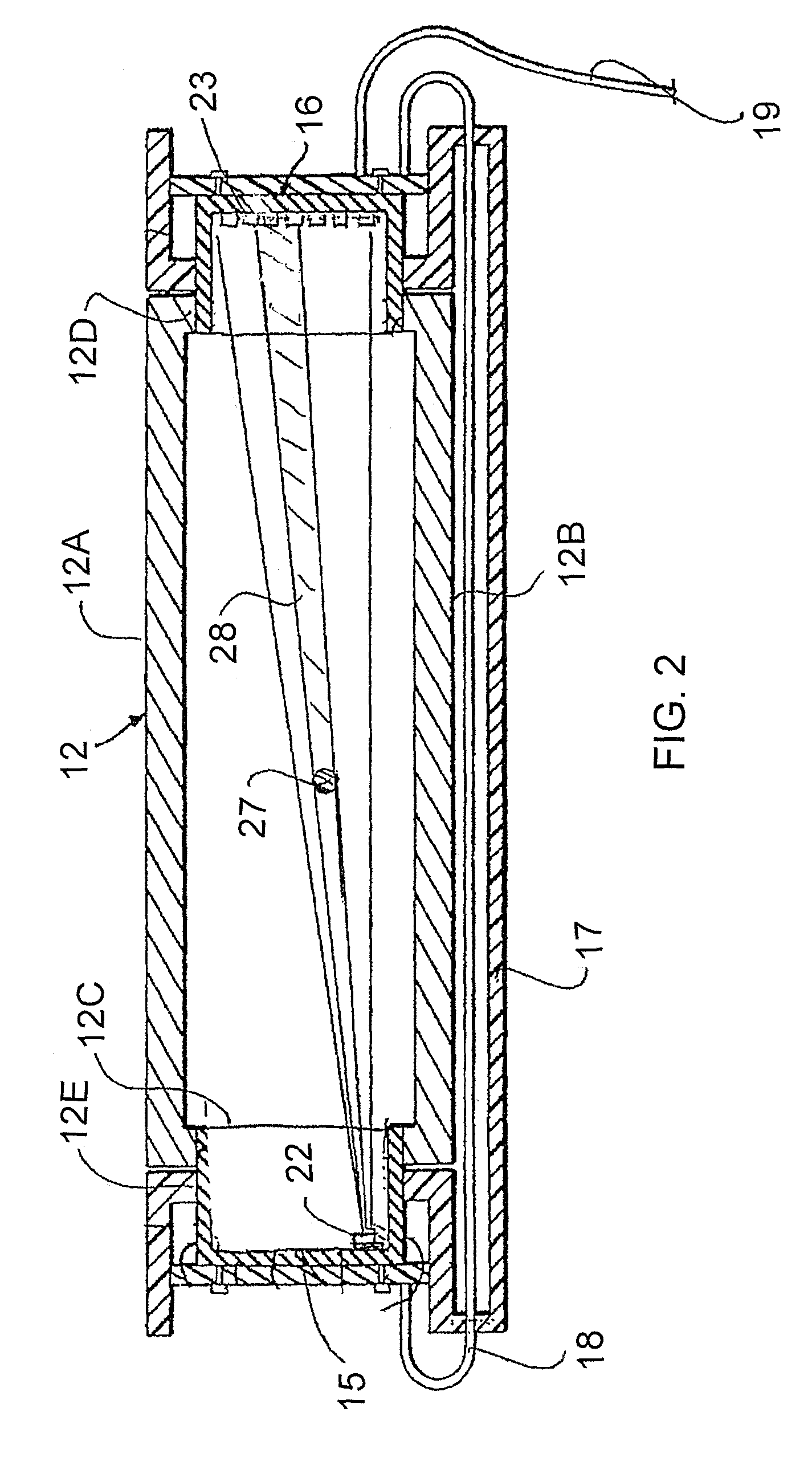
[0073]A first embodiment is shown in FIGS. 2 and 3. In this embodiment, each seed sensor unit includes components 15 and 16 to be mounted on the duct 12. These components are shown in more detail in FIGS. 2 and 3. The duct 12 is rectangular with sides 12A and 12B which are generally longer sides with shorter sides 12C and 12D. On each of the sides 12C and 12D is formed an opening 12E into which a respective one of the components 15 and 16 is mounted for obtaining data relating to the passage of seeds through the duct 12.
[0074]The components 15 and 16 are interconnected by a mounting arrangement 17 which extends along one side 12B to connect the two components together for structural mounting on the duct and also for electrical interconnection using a cable 18 which communicates between the two components and further cable 19 which communicates to the sensor unit 11 associated with the duct 12.
[0075]The components 15 and 16 are mounted in the rectangular opening 12E in each of the si...
second embodiment
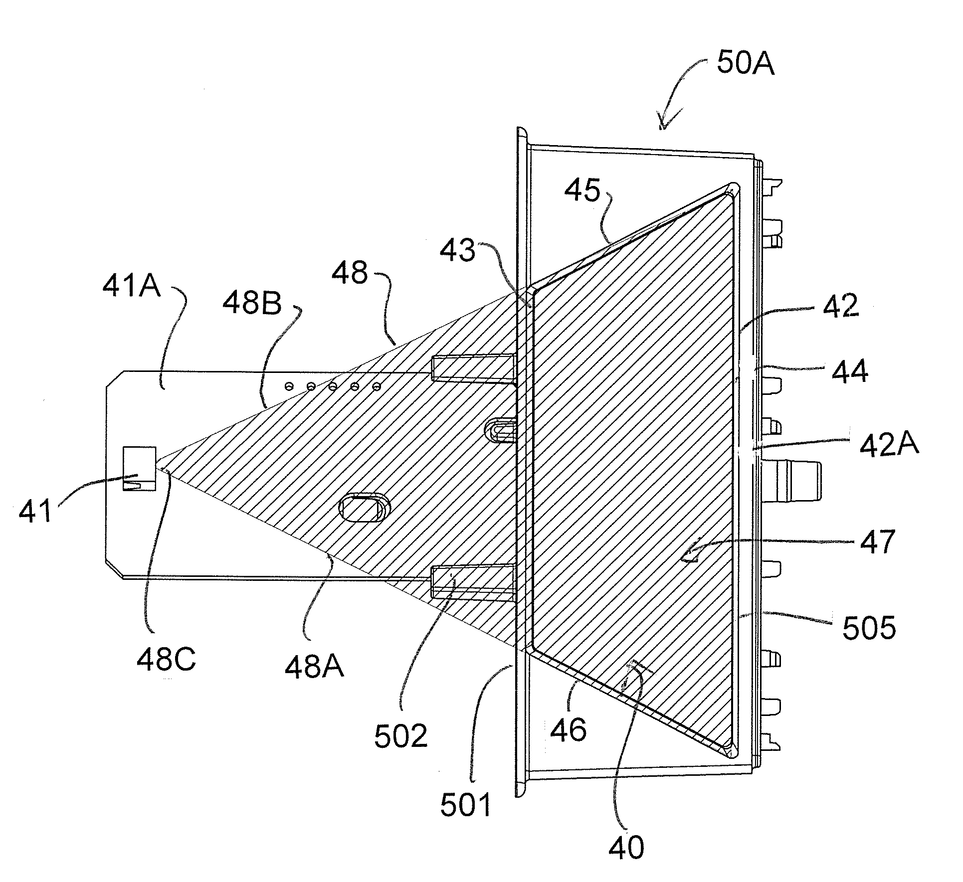
[0083]However it will be appreciated that the point source on one side which is associated with a row on the other side only provides coverage of approximately one half of a duct of rectangular shape. The coverage is approximately triangular from the point source to the row. One way to overcome this problem, as shown in the second embodiment, is to provide a duct which is similarly generally triangular so that the point source and the row effectively cover the whole area of the duct.
[0084]However with ducts that are rectangular it is necessary to provide a second array using a similar row and a separate point source so as to cover the other half of the duct and thus the other triangle which is not covered by the first set. For this reason the second lower set of light components is provided as shown in FIG. 3 including the point source 24 and the receptors 25. In practice the point source 24 is arranged diagonally opposite to the point source 22 so that the light from that point sou...
PUM
 Abstract
Description
Claims
Application Information