
Seed counting apparatus for a planter monitor

a technology of planter monitor and counting apparatus, which is applied in the field of planter monitor, can solve the problems of false counting, dust arising from the discharge end of the duct, and distorting the pulse, and achieve the effects of small photocurrent reduction, reduced photocurrent, and increased incident light reduction

Active Publication Date: 2011-09-22
PARKER HANNIFIN CANADA
View PDF11 Cites 8 Cited by
  • Summary
  • Abstract
  • Description
  • Claims
  • Application Information

AI Technical Summary

Benefits of technology

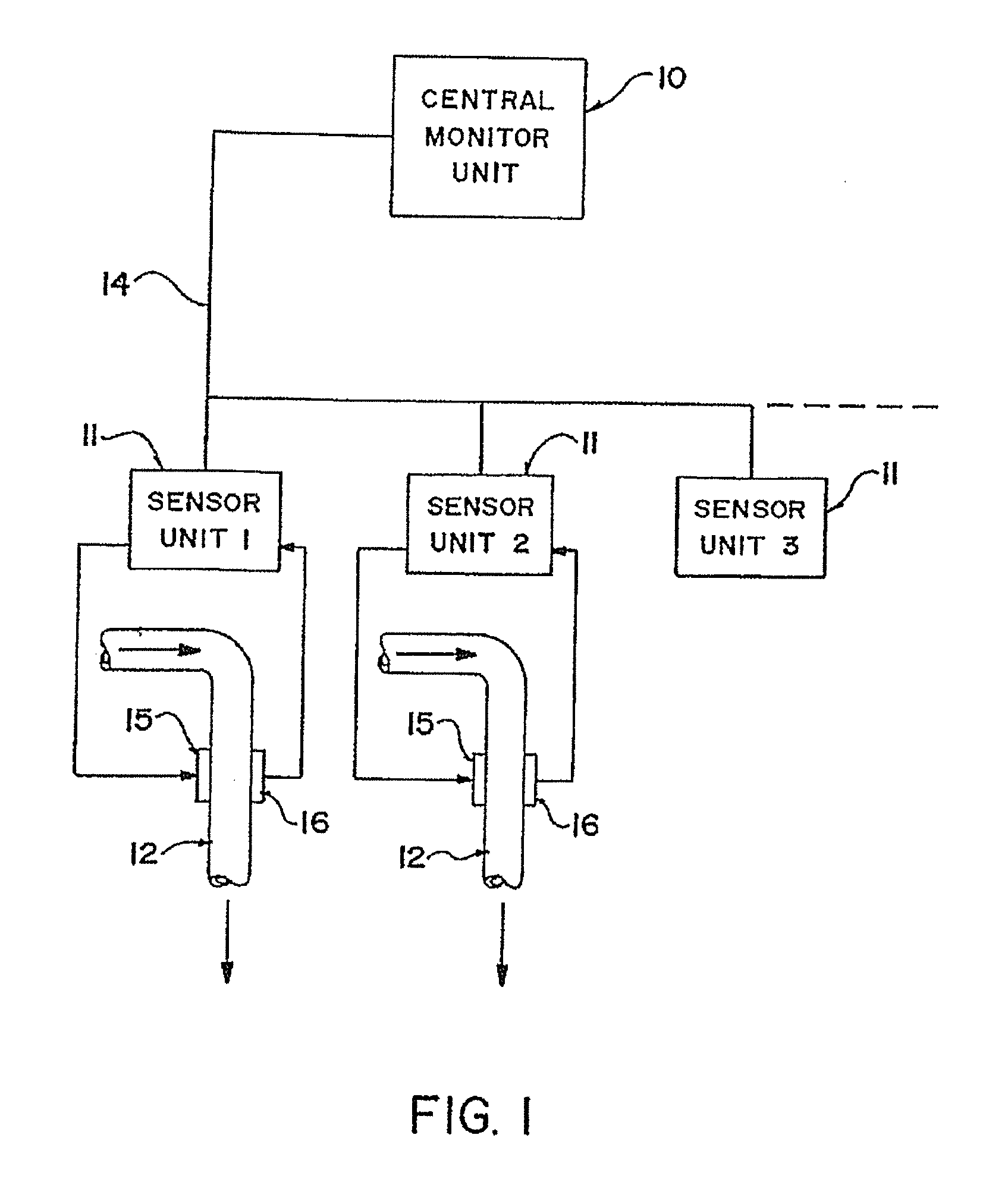
"The present invention provides an improved seed counter for use in a planter monitor. The apparatus includes a duct with light sensors mounted on either side of the duct, a light source also mounted on one side of the duct, and an electronic circuit connected to the light sensors. The light sensors are arranged so that the shadow of a seed falling on one of the sensors causes a change in the output signal of the sensor. The apparatus can distinguish between seeds and dust in the duct by analyzing the amplitude of the momentary change in the output signal. The technical effect of the invention is to provide a more accurate and reliable seed count value in response to movement of seeds in a planter monitor."

Problems solved by technology

As set out in the above patents, one problem which arises in relation to seed counters of this type relates to the accumulation of dust and dirt which can vary the intensity of light normally received by the sensor.
A yet further problem relates to the geometry of the light source and the sensor which can either leave areas of the duct which are not properly monitored or can generate spurious reflections thus distorting the pulses.
One problem which has arisen with arrangements of this type has been that of dust arising from the discharge end of the duct.
Dust is stirred up through the process of planting and this can generate a signal similar to a seed resulting in a false count.
This is due to the fact that dust moving through the tube may block a similar percentage of the light transmitted from the emitter to the detector as would be blocked by a seed.

Method used


Image

  • Seed counting apparatus for a planter monitor
  • Seed counting apparatus for a planter monitor
  • Seed counting apparatus for a planter monitor

Examples


first embodiment

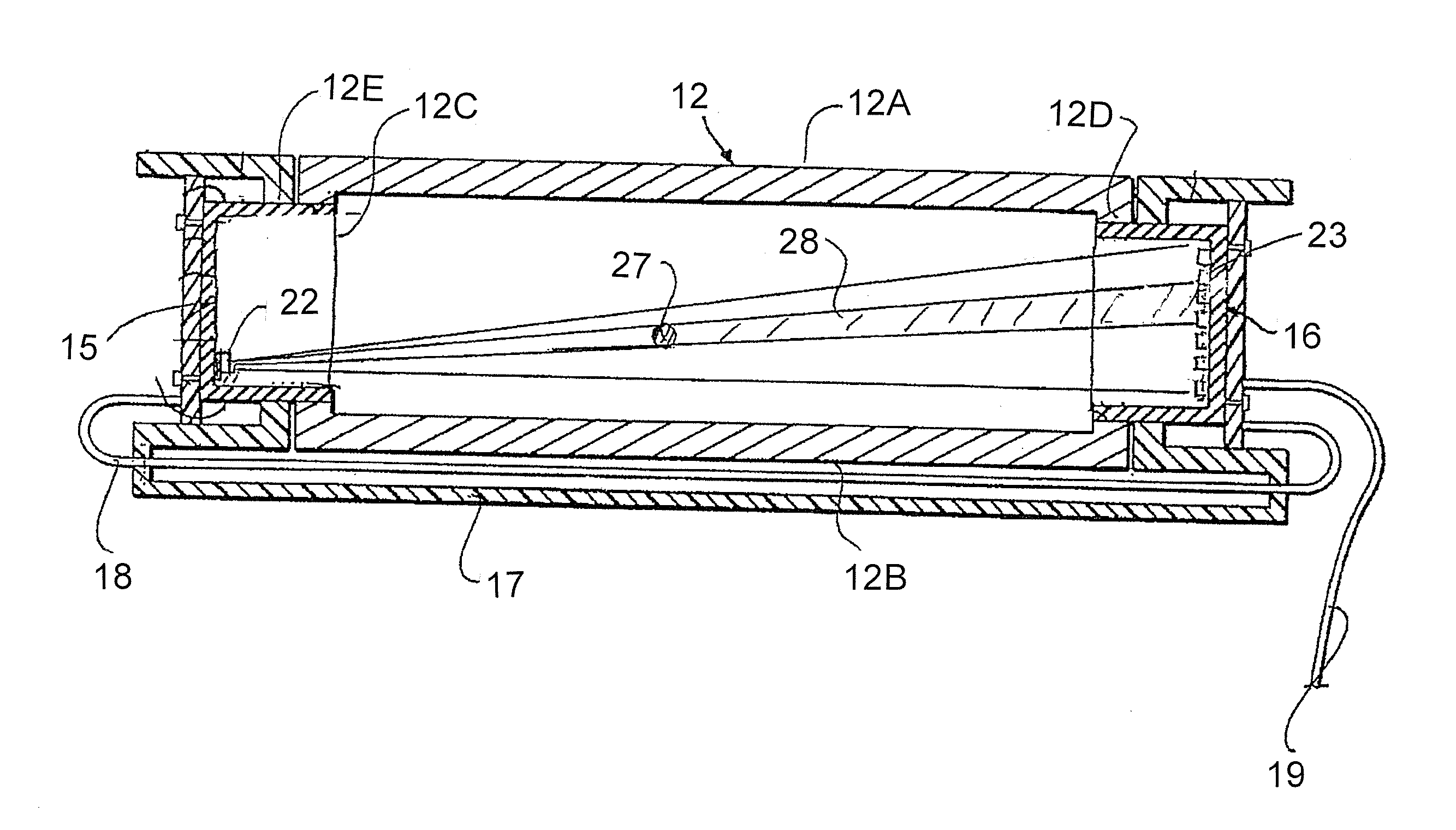
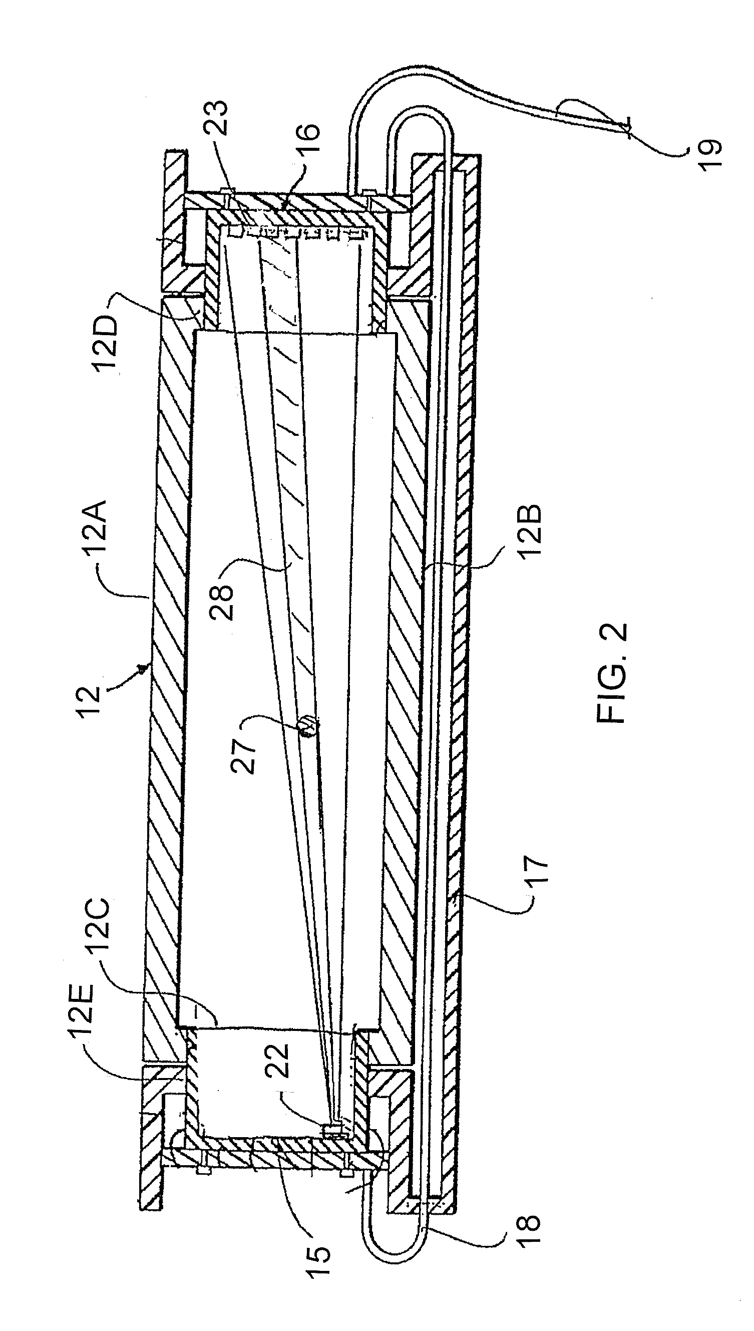
[0073]A first embodiment is shown in FIGS. 2 and 3. In this embodiment, each seed sensor unit includes components 15 and 16 to be mounted on the duct 12. These components are shown in more detail in FIGS. 2 and 3. The duct 12 is rectangular with sides 12A and 12B which are generally longer sides with shorter sides 12C and 12D. On each of the sides 12C and 12D is formed an opening 12E into which a respective one of the components 15 and 16 is mounted for obtaining data relating to the passage of seeds through the duct 12.

[0074]The components 15 and 16 are interconnected by a mounting arrangement 17 which extends along one side 12B to connect the two components together for structural mounting on the duct and also for electrical interconnection using a cable 18 which communicates between the two components and further cable 19 which communicates to the sensor unit 11 associated with the duct 12.

[0075]The components 15 and 16 are mounted in the rectangular opening 12E in each of the si...

second embodiment

[0083]However it will be appreciated that the point source on one side which is associated with a row on the other side only provides coverage of approximately one half of a duct of rectangular shape. The coverage is approximately triangular from the point source to the row. One way to overcome this problem, as shown in the second embodiment, is to provide a duct which is similarly generally triangular so that the point source and the row effectively cover the whole area of the duct.

[0084]However with ducts that are rectangular it is necessary to provide a second array using a similar row and a separate point source so as to cover the other half of the duct and thus the other triangle which is not covered by the first set. For this reason the second lower set of light components is provided as shown in FIG. 3 including the point source 24 and the receptors 25. In practice the point source 24 is arranged diagonally opposite to the point source 22 so that the light from that point sou...


PUM


Abstract

A counter for seeds in a duct includes a first point source transmitter on a first mounting on one side of the duct spaced outwardly from the duct so as to project light through a front wall and a set of phototransistors in a transverse row carried on a second mounting on a rear wall. The side walls of the duct lie on a triangle with an apex at the light source. The phototransistors are connected in series so that the output current is determined by that phototransistor on which the majority of the shadow from the seed falls. In this way the momentary reduction in current output has a larger amplitude to better distinguish from dust in the duct. The duct is formed by a housing attached to the peripheral wall of the metering device with a seed transport tube attached to the bottom of the housing.

Description

[0001]This application claims the benefit under 35 USC 119 of the priority of Provisional Application 61 / 314,247 filed Mar. 16, 2010.[0002]This invention relates to a seed counting apparatus for use in a planter monitor for generating a seed count value in response to a series of seeds moving through a seed transport duct of the planter.BACKGROUND OF THE INVENTION[0003]While various techniques have been explored for detecting seeds falling in a tube, the most commonly used technique is that of a light source and photo sensor which detect the passage of seeds by counting pulses generated by the momentary reduction in light intensity from the steady state intensity caused by the passage of a seed between the light source and the sensor.[0004]The vast majority of products of this type actually manufactured and sold in the marketplace have been manufactured by Dickey-John Corporation and they have obtained issue of a number of patents in this field. In particular the following patents o...

Claims


Application Information

Patent Timeline
Patent Type & Authority Applications(United States)
IPC IPC(8): G06M1/272
CPCG06M1/101A01C7/105
Inventor KJARTANSON, DWIGHT
Owner PARKER HANNIFIN CANADA
Learn More