
Side mirror system with video display

a technology of side mirrors and video displays, which is applied in the field of side mirrors of motor vehicles, can solve the problems of counter-intuitive viewing of the dashboard, limited view, and unprotected rear of the vehicle, and achieve the effect of clear display

Active Publication Date: 2014-03-11
ROBERT MARC
View PDF8 Cites 17 Cited by
  • Summary
  • Abstract
  • Description
  • Claims
  • Application Information

AI Technical Summary

Benefits of technology

[0015]Yet still another object of the present invention is to provide protection for each camera with a shroud mount assembly which further facilitates attachment to a surface of the truck rig. Each mount assembly includes a plurality fastening apertures and shields a camera from projectiles, weather, dust, impact, and the like to keep the camera safe and clean during transport.
[0019]Yet still another object of the present invention is to deter theft of the mirror assembly by deactivating the video display when the system is turned off, thereby discreetly containing the video display behind the glass cover.
[0020]Yet still another object of the present invention is to enable the video display to be safely utilized in direct sunlight by comprising a display of sufficient illuminated brightness and eliminate “wash out”.
[0022]Yet still another object of the present invention is to provide manual control of various functions of the system with a video module located within a cab portion of the truck rig. The video module includes a selector knob allows the user to control various functions including an ON / OFF function, automatic sequential display of each video signal, and selection of a particular view on the display. The video module further includes a multiplexer circuit and a plurality of video display drivers to perform advanced automatic video functions and ensure a clear display.
[0023]Yet still another object of the present invention is to allow connection of additional cameras to the video module, thereby enabling the user to selectively add additional cameras and views as desired at any time.
[0024]Yet still another object of the present invention is to provide a method of installing and utilizing the device that provides a unique means of obtaining the system, attaching the cameras to the truck rig by fastening the mount assemblies, installing the mirror assembly at a driver's side window location, mounting the video module to a dashboard area of the tractor, anchoring and connecting the wiring harness to the various components of the system, turning the system on, viewing the various camera views within the video display, adjusting the positioning of the mount assemblies as necessary, utilizing the heating element to melt and defrost the glass surface during use, and observing the video display portion and glass portion of the mirror assembly while operating the truck rig in a normal manner while backing up or while changing lanes to increase safety and visibility.

Problems solved by technology

However, their view is very limited when changing lanes or backing up into a tight loading dock.
This of course leaves the rear of the vehicle unprotected.
Furthermore, viewing a screen at a dashboard location is counter-intuitive due to the usual lack of a viewing device in that location.
Many such systems do not provide a sufficient plurality of views in order to ensure full vision about a vehicle.
Also, many such systems are unsafe or insufficient for use in large trucks, particularly those without center mounted rear view mirrors.
Furthermore, many such systems do not incorporate a display in a location which is normally viewed by a user when checking for nearby traffic.
In addition, many such systems cannot be easily retrofit to an existing vehicle.
Moreover, may such systems do not allow simultaneous display of all available views.

Method used


Image

  • Side mirror system with video display
  • Side mirror system with video display
  • Side mirror system with video display

Examples


Embodiment Construction

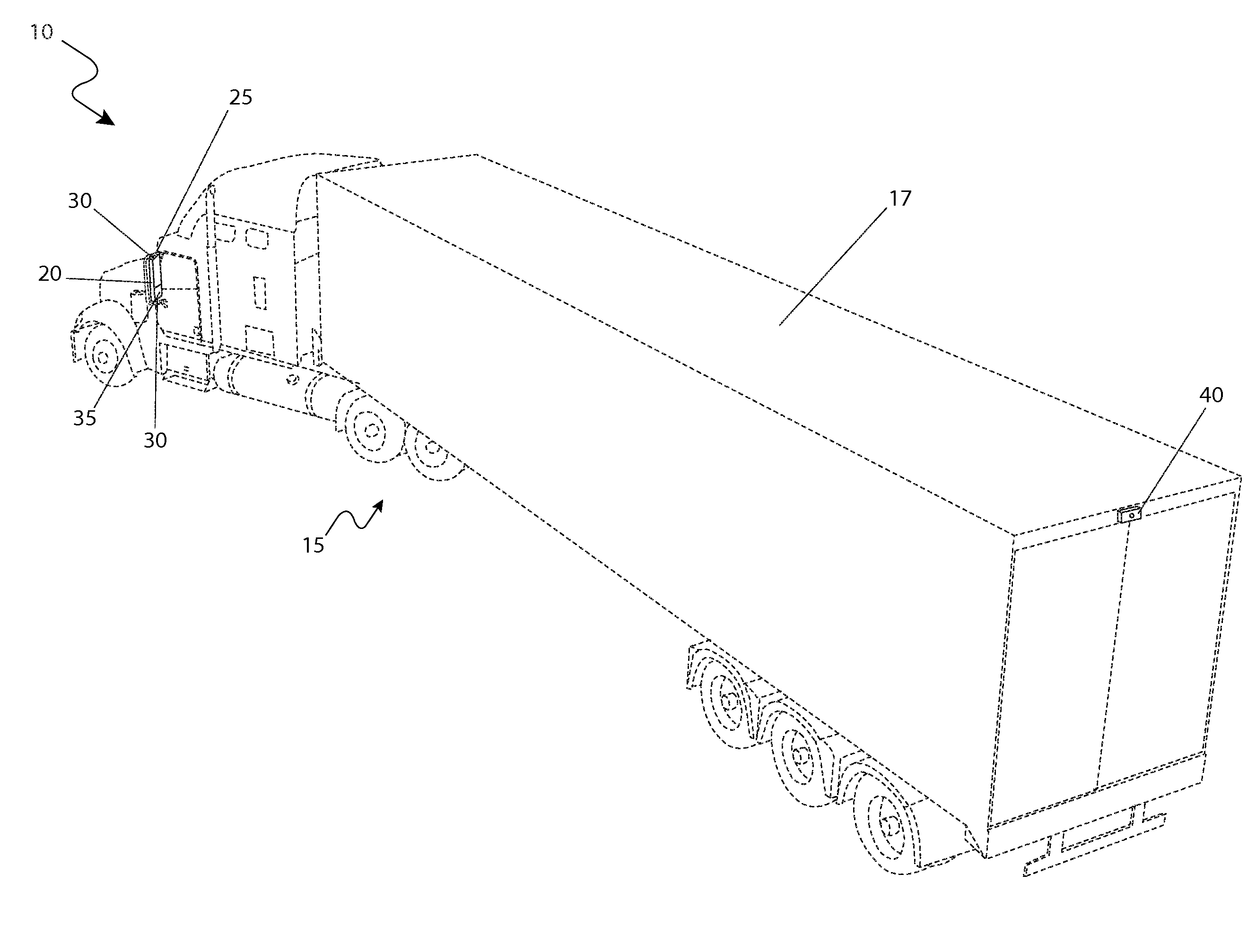
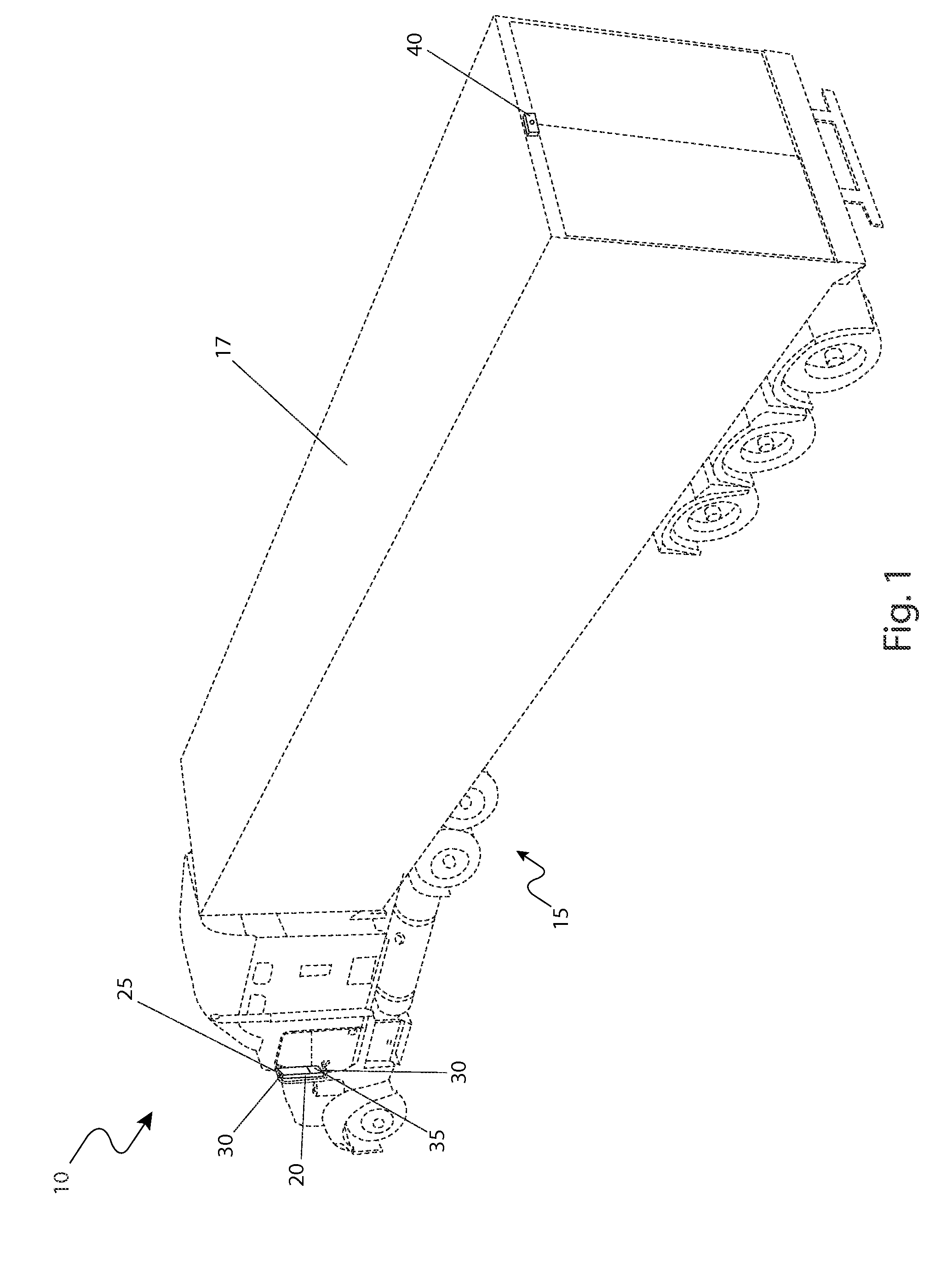
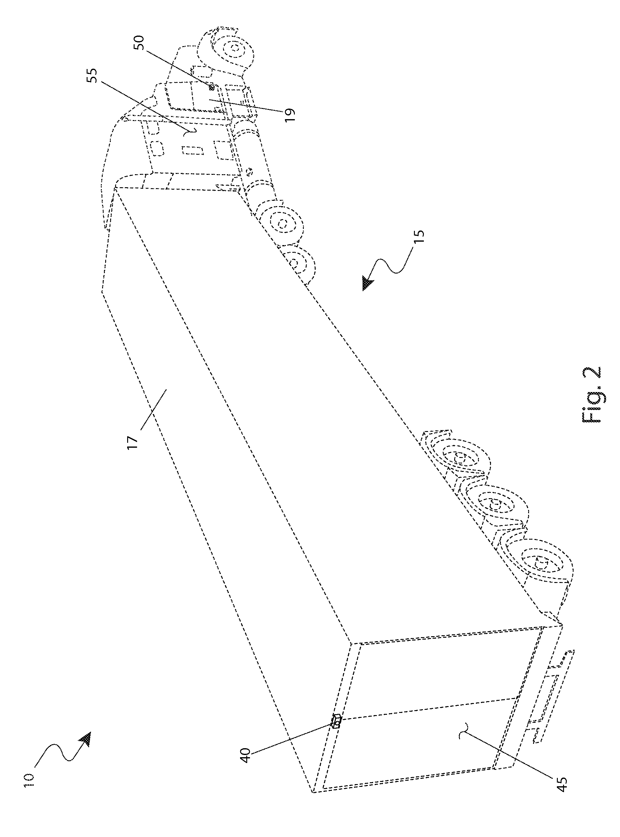
[0068]The best mode for carrying out the invention is presented in terms of its preferred embodiment, herein depicted within FIGS. 1 through 6. However, the invention is not limited to the described embodiment and a person skilled in the art will appreciate that many other embodiments of the invention are possible without deviating from the basic concept of the invention, and that any such work around will also fall under scope of this invention. It is envisioned that other styles and configurations of the present invention can be easily incorporated into the teachings of the present invention, and only one particular configuration shall be shown and described for purposes of clarity and disclosure and not by way of limitation of scope.

[0069]The terms “a” and “an” herein do not denote a limitation of quantity, but rather denote the presence of at least one of the referenced items.

[0070]The present invention describes a device and method for a side mirror system with video display (h...


PUM


Abstract

An apparatus that provides an electronic image of areas around sides and rear of a large tractor trailer rig produced on a weatherproof screen that is located on the lower portion of the driver's side mirror. One (1) camera would be located on the rear of the trailer in a center mounted position, while another camera would be located on a passenger side near the front of the vehicle so that it can see the entire side of the vehicle. The cameras would be equipped with fixed wide-angle lenses. The video signal from each camera would be routed to an automatic switcher that displays each signal for a pre-determined time or allows for the manual selection of either camera on a permanent basis. The video signal is then displayed on the weatherproof monitor portion of the side view mirror. In such a manner the truck driver can look at the mirror and the monitor in order to see all three (3) sides of the vehicle at once. This feature eliminates looking in various directions to check for obstructions while backing up or changing lanes.

Description

RELATED APPLICATIONS[0001]The present invention was first described in and claims the benefit of U.S. Provisional Application No. 61 / 289,110 filed Dec. 22, 2009, the entire disclosures of which are incorporated herein by reference.FIELD OF THE INVENTION[0002]The present invention relates generally to motor vehicle side mirrors, and in particular, to a motor vehicle side mirror assembly including a digital video screen and a plurality of cameras.BACKGROUND OF THE INVENTION[0003]Drivers of larger tractor trailer rigs have a commanding view of the road while traveling in a forward manner down the highway. However, their view is very limited when changing lanes or backing up into a tight loading dock. Mirrors help to some extent, but require the driver to quickly move their head to see both sides of the vehicle. This of course leaves the rear of the vehicle unprotected.[0004]As a result of this deficiency, there are a number of commercially available small electronic cameras that are po...

Claims


Application Information

Patent Timeline
Patent Type & Authority Patents(United States)
IPC IPC(8): H04N7/18B60R11/04
CPCB60R2300/105B60R1/12B60R1/0602B60R2001/1253B60R2300/40B60R2300/70B60R11/04B60R1/00H04N7/181H04N7/188
Inventor ROBERT, MARC
Owner ROBERT MARC
Learn More