
Gas pressure regulator

a pressure regulator and gas technology, applied in the field of gas pressure regulators, can solve the problems of frequent breakage of the type of silencing device, insufficient strength of the mesh the ring is made from to resist high gas speed, and soon breakage, and achieve the effect of being cheap to mak

Active Publication Date: 2014-03-18
EMERSON PROCESS MANAGEMENT SRL
View PDF20 Cites 0 Cited by
  • Summary
  • Abstract
  • Description
  • Claims
  • Application Information

AI Technical Summary

Benefits of technology

The solution enables reliable operation at high gas speeds and with dirty gas flows, is cost-effective, and maintains a compact size, improving the reliability and reducing the weight of the regulator.

Problems solved by technology

When the speed of the gas is high, however, this type of silencing device tends to break frequently.
The mesh the ring is made from is not strong enough to resist high gas speeds and soon breaks.
Moreover, solid particles (such as dust or other debris) which may be carried by the gas leads to mesh wear and failure of the silencing device.
This type of pressure regulator is not therefore suitable for gas flowing at high speeds or containing solid particles, even small diameter particles (where the expression “small diameter” includes particles even smaller than 5 μm in diameter).
This silencing device, however, is cumbersome, heavy and, above all, very expensive.
Furthermore, the production cycle of a silencing device of this kind is extremely lengthy.

Method used


Image

  • Gas pressure regulator
  • Gas pressure regulator
  • Gas pressure regulator

Examples


Embodiment Construction

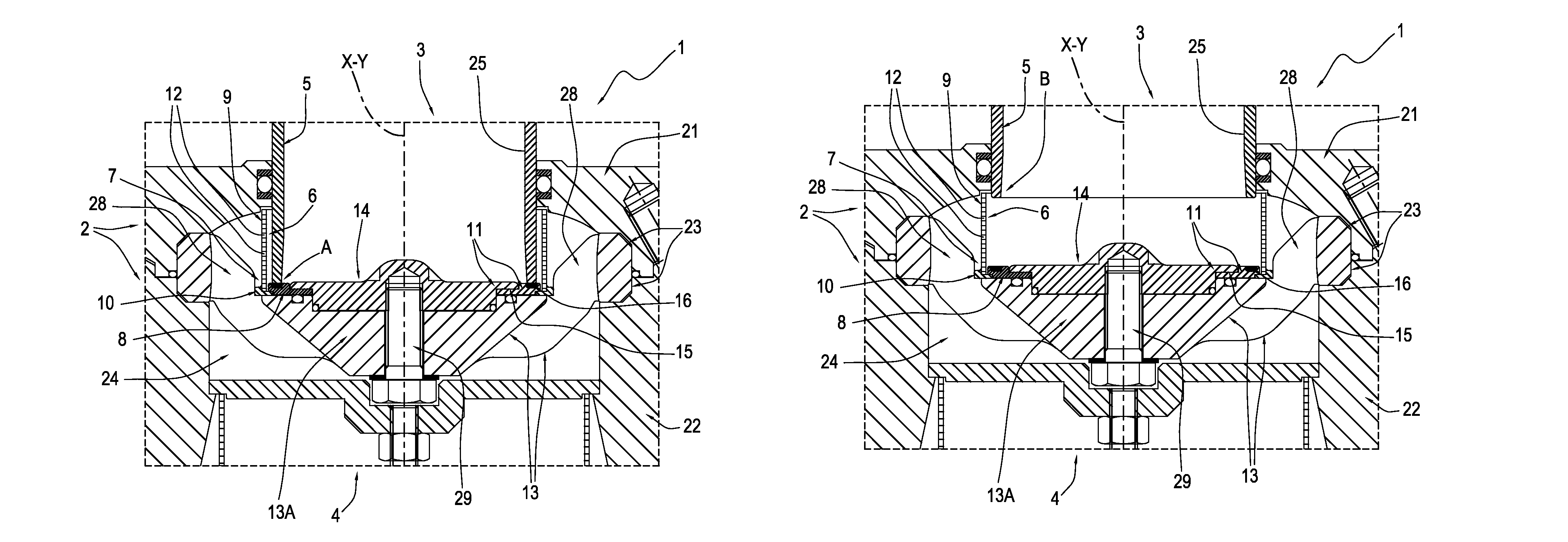
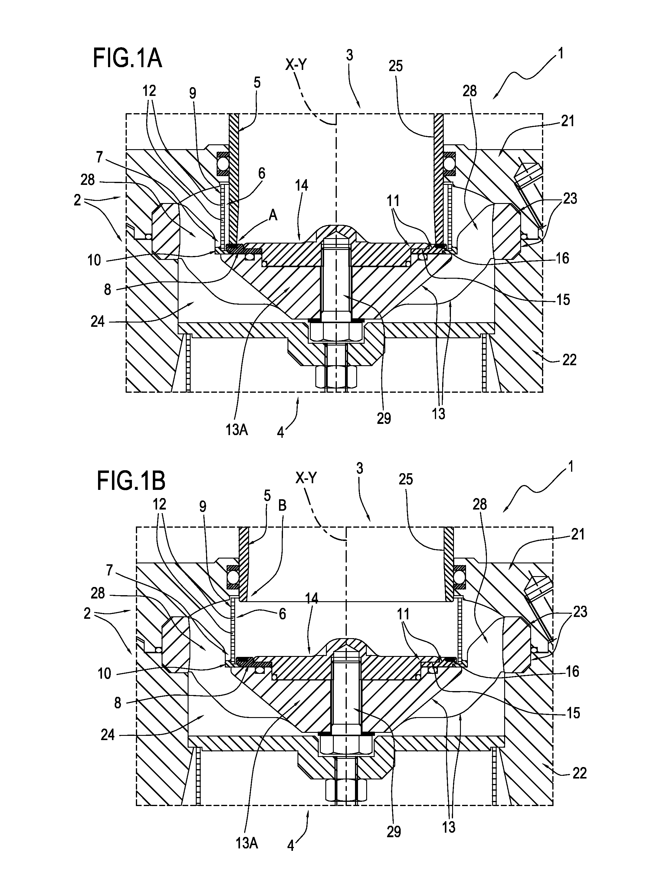
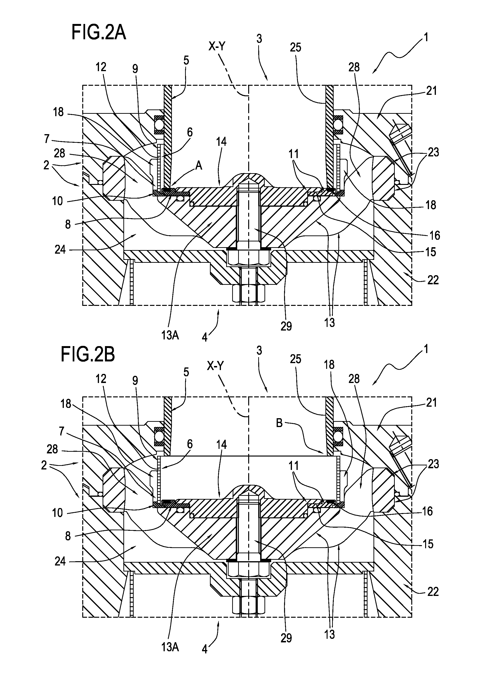
[0034]With reference to the accompanying drawings, the numeral 1 in FIGS. 1A and 1B denotes in its entirety a gas pressure regulator made in accordance with this invention.

[0035]The gas pressure regulator 1 comprises a central body 2 in which a first, gas inlet pipe 3 and a second, gas outlet pipe 4 are fitted (FIGS. 1A and 1B do not show the part where the pipes are fitted in the central body).

[0036]FIGS. 1A and 1B illustrate only part of the central body 2 limited to the relevant central portion.

[0037]The central body 2 comprises a first half-part 21 and a second half-part 22 which are connected to each other in sealed manner.

[0038]The central body 2 has an internal cavity 24 for connecting the pipes 3 and 4.

[0039]The regulator 1 also comprises a shutter 5 which is slidably mounted inside the central body 2.

[0040]The shutter 5 comprises a hollow cylindrical body 25 having a respective central axis Y.

[0041]The hollow cylindrical body 25 of the shutter is mobile relative to the cent...


PUM


Abstract

A gas pressure regulator comprises a central body having a first, gas inlet pipe and a second, gas outlet pipe; a shutter housed at least partially in the central body and mobile to adjust the opening of a section for the passage of the gas between a position (B) in which the section is fully open and a position (A) in which the section is closed; a silencing device located in the central body at the passage section, for reducing the noise created by the passage of the gas; and means for fastening the silencing device to the central body. The silencing device comprises a cylindrical perforated plate to allow the passage of the gas.

Description

CROSS-REFERENCE TO RELATED APPLICATIONS[0001]This application claims the priority benefits of Italian Patent Application Serial No. BO2010A 000063, filed Feb. 4, 2010, the disclosures of which are hereby incorporated by reference.BACKGROUND OF THE INVENTION[0002]This invention addresses the technical sector relating to gas regulators.[0003]More specifically, the invention relates to a gas pressure regulator equipped with a silencing device.[0004]One prior art gas regulator comprises a central body in which an internal cavity is formed.[0005]The central body is connected to a first, gas inlet pipe and a second, gas outlet pipe.[0006]The regulator also comprises a shutter which is slidably fitted inside the cavity in the central body.[0007]The shutter is mobile in the direction of its axis to adjust the opening of the gas passage section.[0008]The shutter is mobile between a fully open position, where it allows the maximum flow of gas between the inlet pipe and the outlet pipe, and a ...

Claims


Application Information

Patent Timeline
Patent Type & Authority Patents(United States)
IPC IPC(8): F16K47/08
CPCF16K47/08Y10T137/0396Y10T137/86759Y10T137/8376
Inventor ZECCHI, STEFANOBORGHESANI, OMERO
Owner EMERSON PROCESS MANAGEMENT SRL
Learn More