Container seal with radio frequency identification tag, and method of making same

a technology of radio frequency identification and container seal, which is applied in the direction of container/bottle construction, special data processing applications, packaged goods types, etc., can solve the problems of tampering, impede the migration of air and moisture into the interior of the container, and add to the cost ultimately borne by the end user

Active Publication Date: 2014-03-18
EAGILE
View PDF25 Cites 5 Cited by
  • Summary
  • Abstract
  • Description
  • Claims
  • Application Information

AI Technical Summary

Benefits of technology

[0016]A container closure assembly includes a closure, an inner seal, and a radio frequency identification tag. The inner seal comprises a sealable file laminated to a metallic foil, and includes a first surface for sealing engagement with a container sealing surface, and a second, opposed surface for non-sealing engagement with a backing liner, a facing liner, or a glued-in closure liner. The radio frequency identification tag includes a microprocessor electrically coupleable with an antenna for receiving, storing, and transmitting digitized information. The inner seal minimizes migration of fluids between a container interior volume and an exterior of a container when the inner seal is sealingly engaged with a container sealing surface. The radio frequency identification tag is includable in the closure assembly without the closure assembly electromagnetically interfering with the receiving, storing, or transmitting of the digitized information.

Problems solved by technology

All of this may add to the cost ultimately borne by the end-user, thereby increasing the value of the product enclosed by a container and closure assembly.
Thus, closure assemblies may also include functionalities that impede the migration of air and moisture into the interior of the container.
Such seals are adapted so that the seal must be removed, destroyed, or distorted to gain initial access to the contents, thus indicating that tampering may have taken place.
Nevertheless, tampering agents can replace or recreate a sealing liner so expertly that the deception may very likely be undiscovered.
This may further complicate closure assembly fabrication and container filling by requiring that the fabricator responsible for adding the RFID tags to the final container and / or closure assembly perform additional operations on the RFID tags, such as encoding, verification, quality control, and the like.
This can lead to inefficiencies and increased costs, and can complicate customization of the RFID tags.
However, as discussed above, the higher permeability of polymeric liners may render their use undesirable.
While in many cases satisfactory performance of the RFID tag can be provided with this configuration, the composite liner is more permeable in those areas without an overlying metallic liner, effectively rendering the entire sealing liner relatively permeable, and thereby defeating the purpose of a metallic liner.
However, sealing liner fabrication methods may fail to accommodate satisfactory integration of the RFID tag with the sealing liner.

Method used


Image

  • Container seal with radio frequency identification tag, and method of making same
  • Container seal with radio frequency identification tag, and method of making same
  • Container seal with radio frequency identification tag, and method of making same

Examples


first embodiment

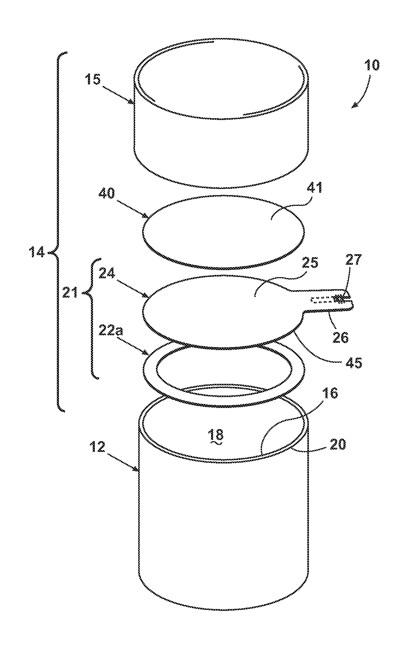
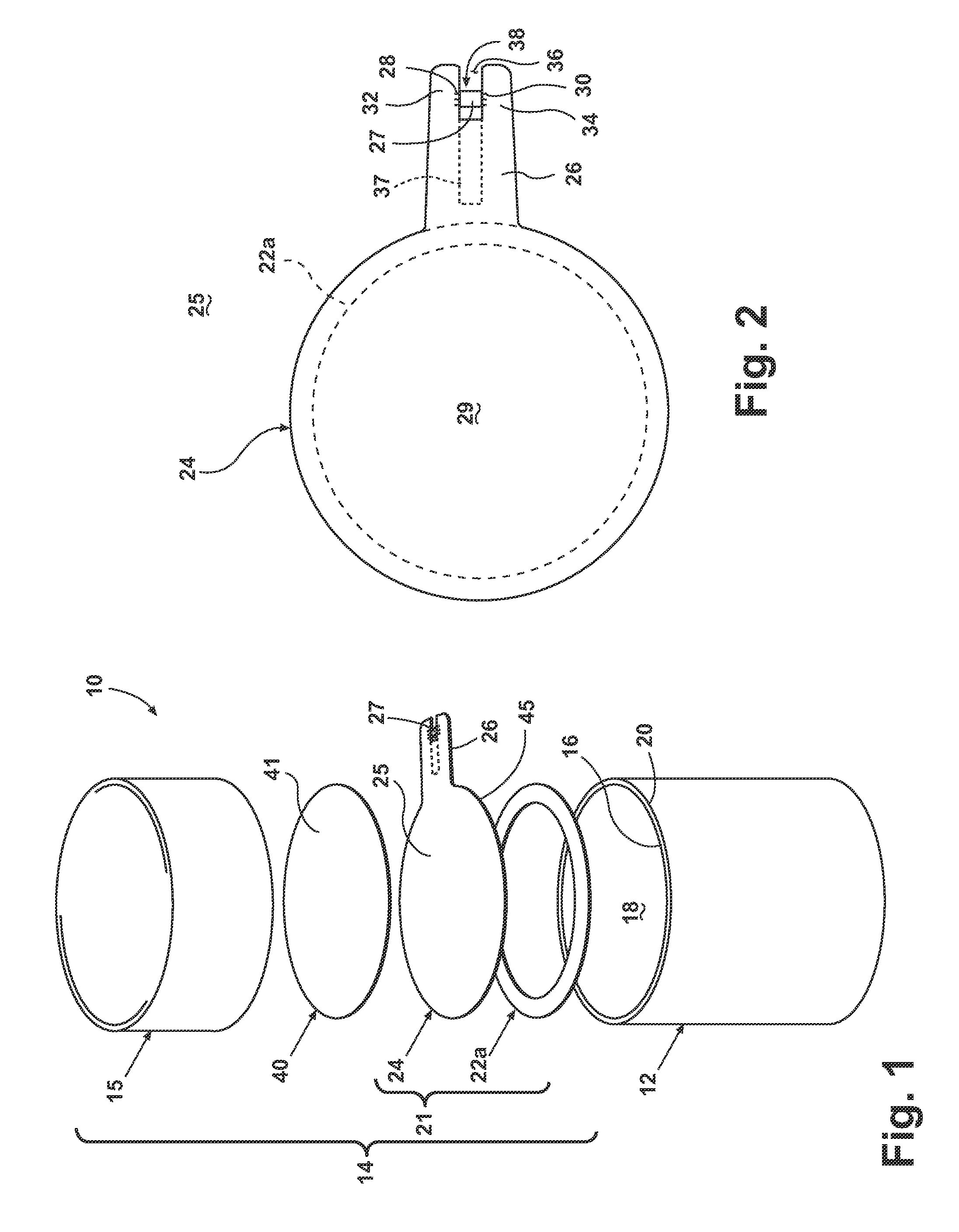
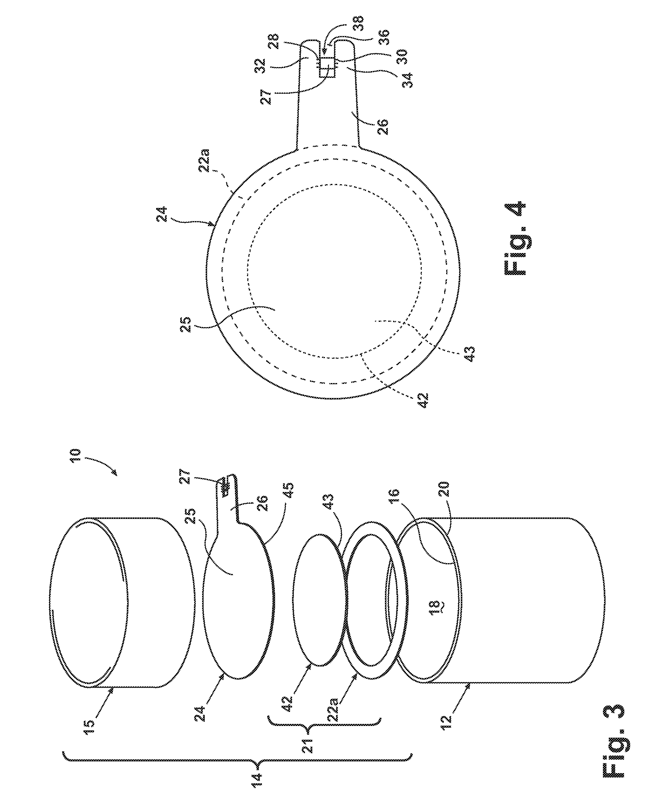
[0070]The configuration of the mounting tab 26 can be as disclosed for the first embodiment RFID tag 25. The metallic foil 24 and mounting tab 26 can perform as an antenna for the microprocessor 27, which can be isolated from the metallic foil 24 by the fold-under isolation liner 42, except through the mounting contacts 28, 30.

[0071]FIGS. 5 and 6 illustrate a third exemplary embodiment of a closure assembly 14, including an RFID tag 25, generally as described for the first exemplary embodiment, and a fold-under isolation pad 44. The fold-under isolation pad 44 is illustrated as comprising a rectilinear “patch” affixed to the underside 45 of the metallic foil 24, and is utilized in place of the fold-under isolation liner 42. The fold-under isolation pad 44 can have a size and configuration sufficient to isolate the microprocessor 27 from the metallic foil 24 when the mounting tab 26 is folded under. Optionally, the isolation pad 44 can be affixed to the upper side of the metallic foi...

sixth embodiment

[0077]Referring now to FIG. 9, a sixth exemplary embodiment of a closure assembly 14 according to the invention is illustrated. The sixth embodiment is similar to the previously described embodiments, and includes the container 12, the closure 15, a sealable film 22b (the illustrated sealable films 22a, 22b can be utilized in the alternative), the metallic foil 24, a pull-tab liner 76, and a backing liner 78, also referred to as a “wad.” The closure assembly 14 can include different elements than shown in FIG. 9 depending upon, for example, factors such as the pertinent properties of the item(s) to be contained, and the type (e.g. moisture, tampering) and degree of protection specified.

[0078]The pull-tab liner 76 can comprise a multi-layered liner incorporating a pull-tab 82 for grasping by a user to remove the closure assembly 14 and gain access to the interior space 18 of the container 12. The pull-tab liner 76 can be interlayered with the sealable film 22 and the metallic foil 24...


PUM

PropertyMeasurementUnit
interior volumeaaaaaaaaaa
volumeaaaaaaaaaa
radio frequencyaaaaaaaaaa

Abstract

A container closure assembly includes a closure, an inner seal, and a radio frequency identification tag. The inner seal comprises a sealable film laminated to a metallic foil, and includes a first surface for sealing engagement with a container sealing surface, and a second, opposed surface for non-scaling engagement with a backing liner, a facing liner, or a glued-in closure liner. The radio frequency identification tag includes a microprocessor electrically coupleable with an antenna for receiving, storing, and transmitting digitized information. The inner seal minimizes migration of fluids between a container interior volume and an exterior of a container when the inner seal is sealingly engaged with a container sealing surface. The radio frequency identification tag is includable in the closure assembly without the closure assembly electromagnetically interfering with the receiving, storing, or transmitting of the digitized information.

Description

CROSS-REFERENCE TO RELATED APPLICATIONS[0001]This application claims the benefit of U.S. Applications No. 61 / 323,915, filed Apr. 14, 2010, and No. 61 / 360,550, filed Jul. 1, 2010, each of which is incorporated by reference herein in its entirety.BACKGROUND OF THE INVENTION[0002]1. Field of the Invention[0003]The invention relates to a container closure assembly having an integral radio frequency identification tag.[0004]2. Description of the Related Art[0005]Closable containers are utilized for a multitude of household and commercial products. Closures, such as threaded and flip-top caps, hinged closures, dispensing closures, and the like, are installed after filling the container with a selected product. Closures can have a relatively simple structure, or can include multi-layered liners providing selected functionality. A finished closure assembly may be a multi-part assembly, and may include, for example, a hard-shelled outer closure adapted for reclosable engagement with a contai...

Claims


Application Information

Patent Timeline
Patent Type & Authority Patents(United States)
IPC IPC(8): G08B23/00
CPCB65D2203/10B65D53/04B65D51/24B65D77/20G06K19/07B65D51/18Y10T428/24802Y10T428/2817Y10T428/14
Inventor PHANEUF, PETERBURNS, GARY P.ISABELL, MICHAEL
Owner EAGILE
Why Eureka
Try Eureka