Distance measurement method and system, and processing software thereof

a distance measurement and distance measurement technology, applied in the field of distance measurement, can solve the problems of damage to objects and inability to meet expensive objects with contact distance measurement instruments, and achieve the effect of high reliability

Active Publication Date: 2014-03-18
SAMSUNG ELECTRONICS CO LTD
View PDF9 Cites 2 Cited by
  • Summary
  • Abstract
  • Description
  • Claims
  • Application Information

AI Technical Summary

Benefits of technology

[0005]Therefore, the present invention provides a distance measurement method and a distance measurement system, which can carry out a 3D non-contact distance measurement and have higher reliability.
[0006]In addition, the present invention further provides storage media with a processing software, which can process data of the distance measurement system, and reliably compute a position of an object.
[0011]Since the present invention performs the distance measurement based on images with a speckle pattern reflected by a plurality of reference planes and an object, thus a 3D non-contact distance measurement can be carried out. In addition, since the present invention compares the most similarity score with a threshold value, thus a high reliability is obtained.

Problems solved by technology

Although the contact distance measurements have been very precise, as the contact distance measurement should contact the object, probes of the contact distance measurement instruments may damage the object.
Therefore, the contact distance measurement instruments are not suitable for expensive objects.

Method used


Image

  • Distance measurement method and system, and processing software thereof
  • Distance measurement method and system, and processing software thereof
  • Distance measurement method and system, and processing software thereof

Examples


first embodiment

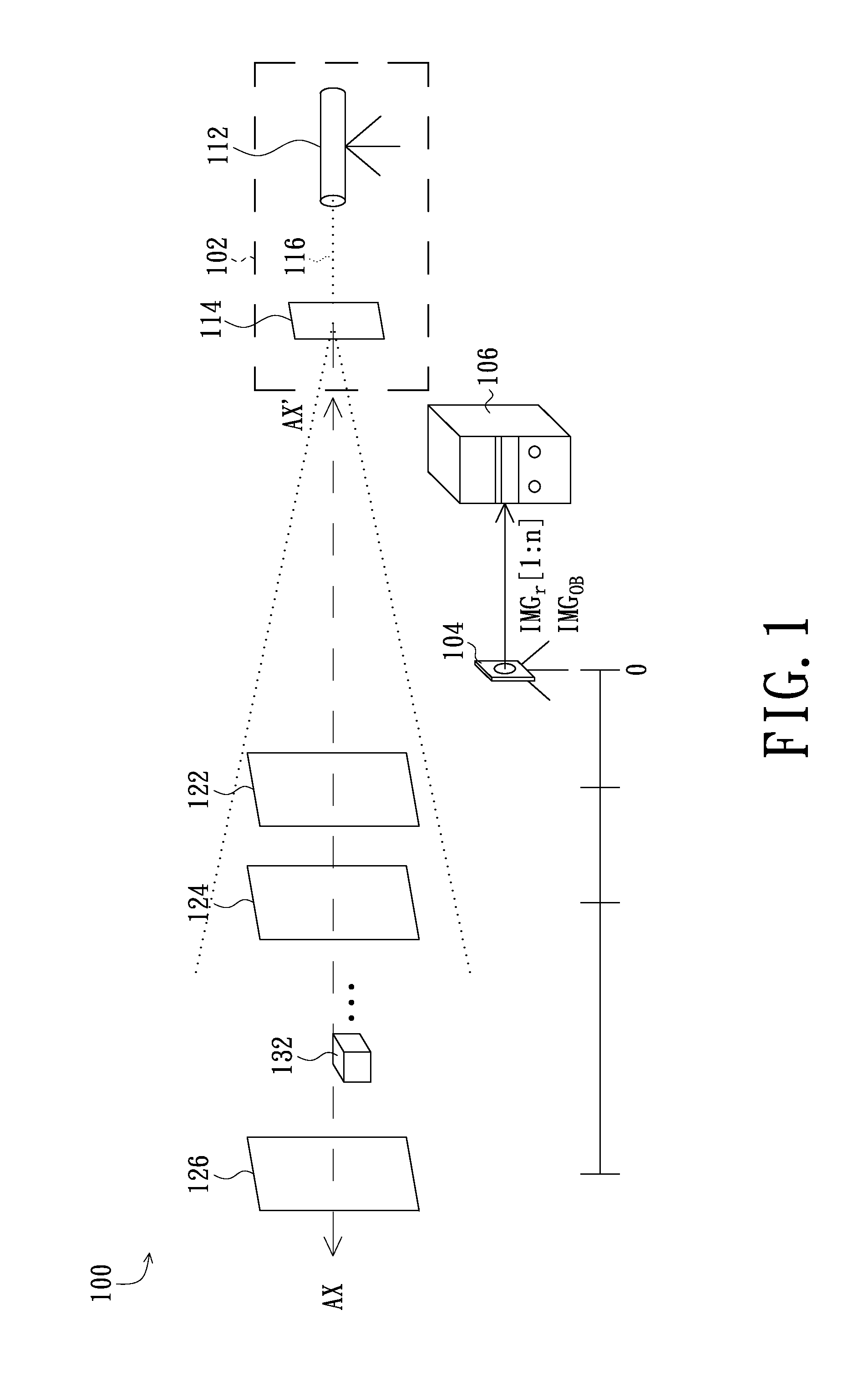
[0022]FIG. 1 shows a distance measurement system in accordance with a Referring to FIG. 1, the distance measurement system 100 of the present embodiment includes a light source module 102, an image capture device 104 and a processing module 106. The light source module 102 is capable of providing a light beam having a speckle pattern to a detectable region, wherein the light source module 102 may be a planar light source module. In addition, the image capture device 104 can be coupled to the processing module 106.

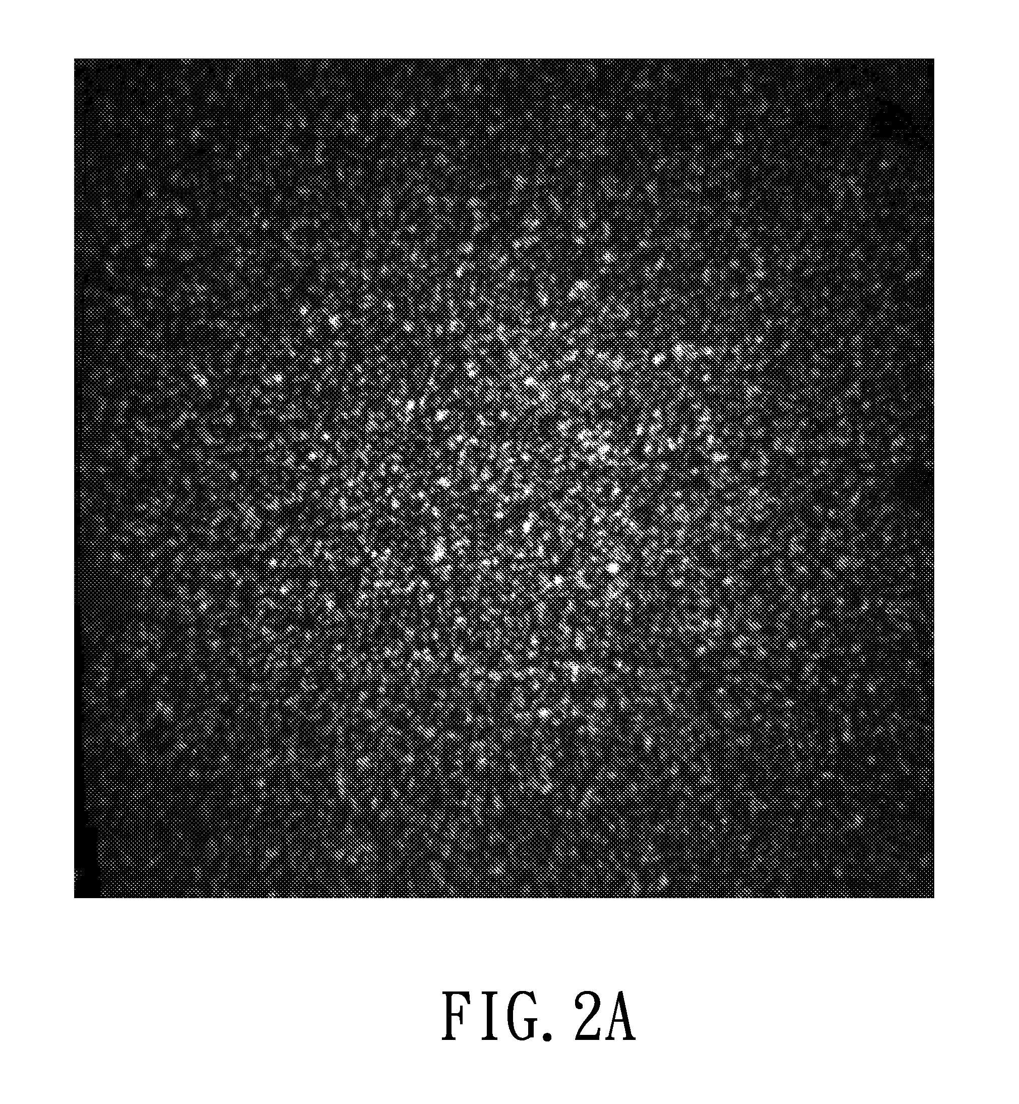
[0023]In the present embodiment, the light source module 102 includes a laser light source 112 and a light diffusing element 114. Wherein, the laser light source 112 can be a gas laser, e.g., a He—Ne laser, or a semiconductor laser. In addition, the light diffusing element 114 can be a diffusion sheet, a piece of ground glass or a diffraction element. When the laser light source 112 projects a laser light beam 116 to the light diffusing element 114, the laser beam 116 woul...

third embodiment

[0034]FIG. 5 shows a distance measurement system in accordance with the present invention. Referring to FIG. 5, in the distance measurement system 500 of the present embodiment, the image capture device 104 is arranged beside the laser light source 112.

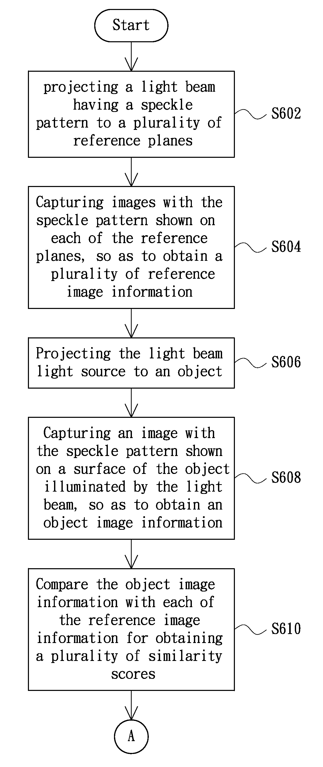
[0035]FIGS. 6A and 6B are flow charts of a distance measurement method in accordance with a preferred embodiment of the present invention. Referring to FIGS. 6A and 6B, the distance measurement method of the present embodiment may first include step S602, i.e., project a light beam having a speckle pattern provided from a planar light source module to a plurality of reference planes, wherein the speckle pattern has a plurality of speckles. Next, as step S604, capture an image having the speckle pattern shown on each of the reference planes, so as to obtain a plurality of reference image information associated with the reference planes. In addition, go to step S606, project the light beam having the speckle pattern to an object. Next, ...


PUM


Abstract

A distance measurement system and method are provided. The distance measurement method first projects a light beam with a speckle pattern to reference planes and an object to allow the reference planes and a surface of the object each have an image of the speckle pattern, the speckle pattern having a plurality of speckles. Next, images of the speckle pattern reflected by the reference planes are captured to generate reference image information, and an image of the speckle pattern reflected by the surface of the object is captured to generate an object image information. A processing module which may be a processing software can compare the object image information with the reference image information to obtain several similarity scores. If the most the most similarity score is greater than a threshold value, the processing module identifies the corresponding reference plane, thereby computing the position of the object.

Description

CROSS-REFERENCE TO RELATED APPLICATION[0001]This application claims the priority benefit of Taiwan application serial no. 099129974, filed on Sep. 3, 2010. The entirety of the above-mentioned patent application is incorporated herein by reference and made a part of this specification.FIELD OF THE INVENTION[0002]The present invention relates to distance measurement, and more particularly to a three dimensional (3D) distance measurement method and system.BACKGROUND OF THE INVENTION[0003]Currently, distance measurements include contact distance measurements and non-contact distance measurements. Wherein the contact distance measurements are conventional, and an example of which is called coordinate measuring machine (CMM). Although the contact distance measurements have been very precise, as the contact distance measurement should contact the object, probes of the contact distance measurement instruments may damage the object. Therefore, the contact distance measurement instruments are...

Claims


Application Information

Patent Timeline
Patent Type & Authority Patents(United States)
IPC IPC(8): G06K9/00
CPCG01B11/002G01S17/08G01B11/14G06K9/64
Inventor YANG, SHU-SIANGU, REN-HAUCHEN, HSIN-CHIAHUANG, SEN-HUANG
Owner SAMSUNG ELECTRONICS CO LTD
Why Eureka
Try Eureka