System for heating a fuel

a fuel heating and fuel technology, applied in the field of fuel consumed by a combustion turbine engine, can solve the problems of heat within the discharged exhaust not being reclaimed, source considered a parasitic load on the combustion turbine engine,

Active Publication Date: 2014-03-25
GE INFRASTRUCTURE TECH INT LLC
View PDF10 Cites 8 Cited by
  • Summary
  • Abstract
  • Description
  • Claims
  • Application Information

AI Technical Summary

Problems solved by technology

This energy source is considered a parasitic load on the combustion turbine engine.
Hence, the heat within the discharged exhaust is not reclaimed.

Method used


Image

  • System for heating a fuel
  • System for heating a fuel
  • System for heating a fuel

Examples


Embodiment Construction

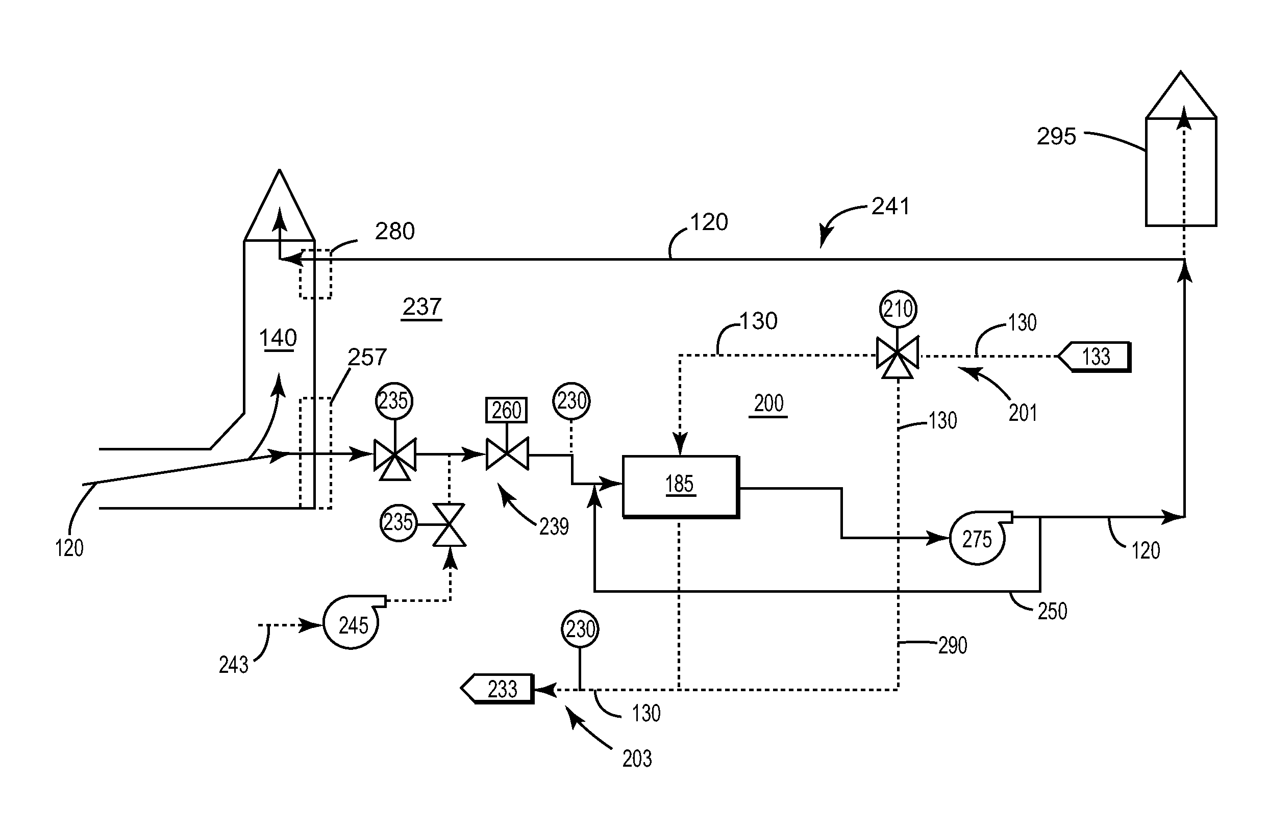
[0011]One or more specific embodiments of the present invention will be described below. In an effort to provide a concise description of these embodiments, all features of an actual implementation may not be described in the specification. It should be appreciated that in the development of any such actual implementation, as in an engineering or design project, numerous implementation-specific decisions are made to achieve the specific goals, such as compliance with system-related and / or business-related constraints, which may vary from one implementation to another. Moreover, it should be appreciated that such effort might be complex and time consuming, but would nevertheless be a routine undertaking of design, fabrication, and manufacture for those of ordinary skill having the benefit of this disclosure.

[0012]Detailed example embodiments are disclosed herein. However, specific structural and functional details disclosed herein are merely representative for purposes of describing ...


PUM


Abstract

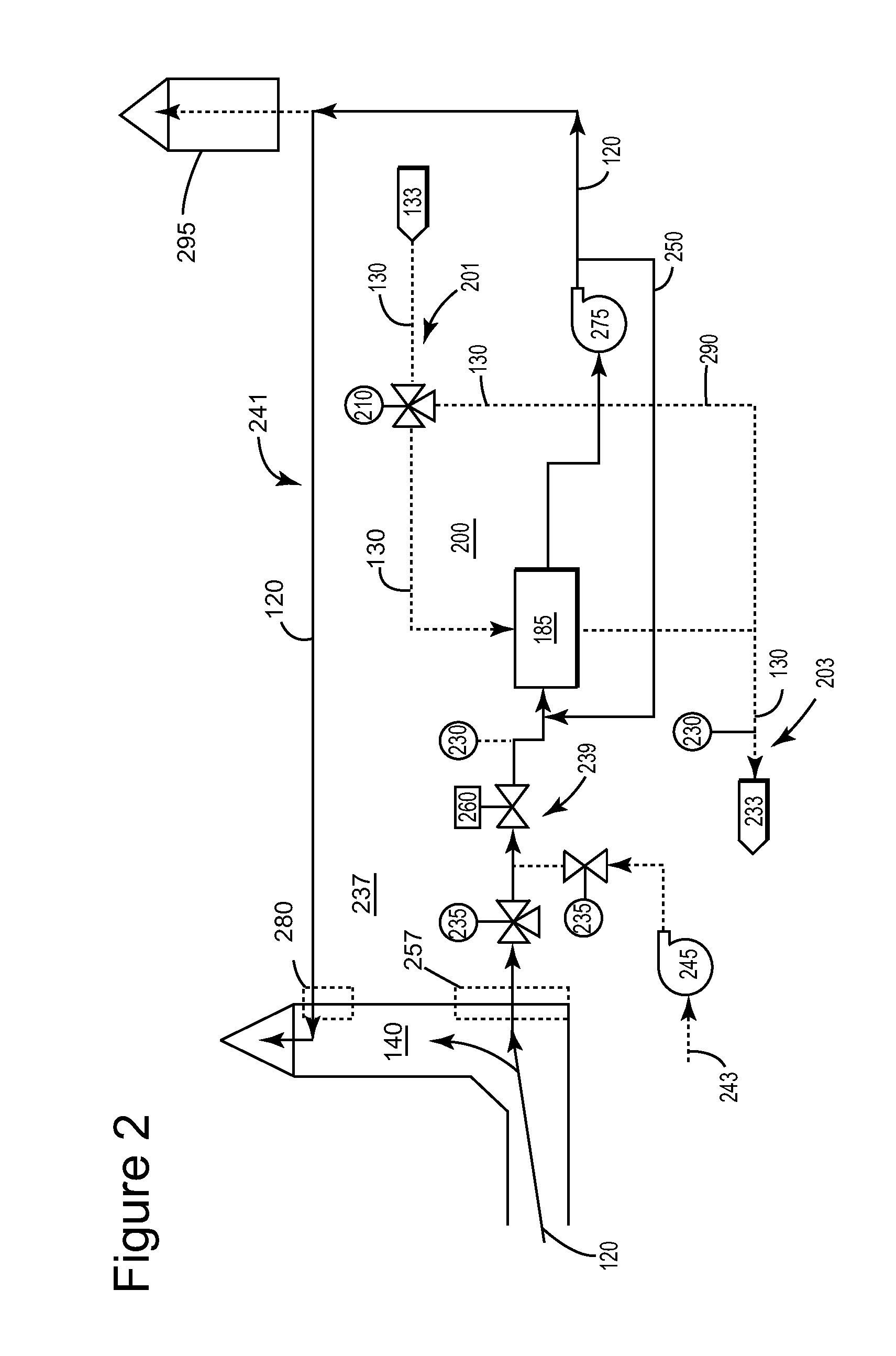
An embodiment of the present invention takes the form of a system that uses exhaust from the combustion turbine engine to heat the fuel gas consumed by a combustion turbine engine. The benefits of the present invention include reducing the need to use a parasitic load to heat the fuel gas.

Description

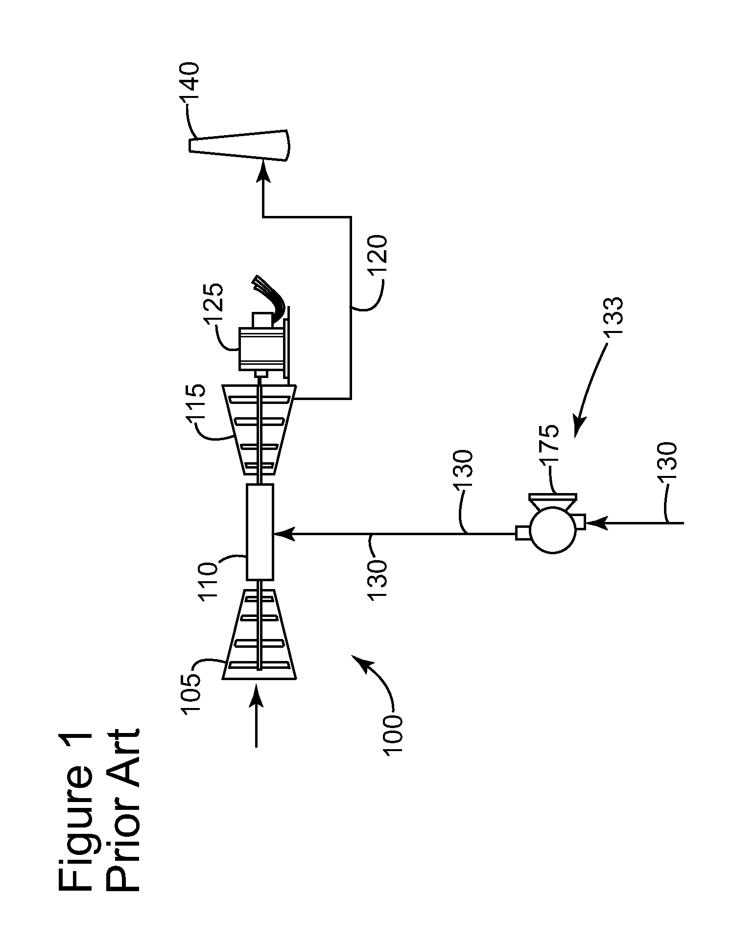
BACKGROUND OF THE INVENTION[0001]The present invention relates to the fuel consumed by a combustion turbine engine during operation; and more particularly to a system that uses exhaust from a combustion turbine engine to heat the fuel.[0002]The temperature of the fuel consumed by a combustion turbine engine is generally required to be within a specific range. The fuel may include, but is not limited to, various type of fuel oil, a natural gas, or a synthetic gas. The combustion systems on some combustion turbine engines require heated natural gas. Generally, the supplied natural gas is not heated. Here, a fuel heater is used to increase the temperature of the natural gas to meet the combustion turbine engine requirements. The fuel heater requires an energy source for operation. This energy source is considered a parasitic load on the combustion turbine engine.[0003]The exhaust generated by the combustion turbine engine is discharged to the ambient environment. Hence, the heat within...

Claims


Application Information

Patent Timeline
Patent Type & Authority Patents(United States)
IPC IPC(8): F02C7/08F02G1/00
CPCF02C7/14F05D2260/213F02C7/224F02C7/141
Inventor BILTON, TIMOTHY RUSSELLBALL, JR., DAVID WESLEYGALLAGHER, BRIAN MICHAELRENDO, KOREY FREDERICMOBLEY, JR., GARY CLETUS
Owner GE INFRASTRUCTURE TECH INT LLC
Why Eureka
Try Eureka