Bracket and spine mounted cornice and method of use

a cornice and bracket technology, applied in the field of cornices, can solve the problems of introducing mechanical failure areas and a large amount of stress on the brack

Inactive Publication Date: 2014-03-25
CORNICESMITH
View PDF26 Cites 19 Cited by
  • Summary
  • Abstract
  • Description
  • Claims
  • Application Information

AI Technical Summary

Benefits of technology

[0008]Conventional brackets typically have a 90 degree angle, forming a vertical support for hardware, like a cornice, blind, or other window treatment. This places a large amount of stress on the bracket, introducing areas of mechanical failure. As such, the disclosed bracket addresses these issues through a novel design. The bracket has a flat plate with an upper edge and lower edge, and a wall face and indicator face, and a clip disposed on the lower edge and bent toward the indicator face, forming a support face

Problems solved by technology

This places a large amount of stress on the br

Method used


Image

  • Bracket and spine mounted cornice and method of use
  • Bracket and spine mounted cornice and method of use
  • Bracket and spine mounted cornice and method of use

Examples


example 1

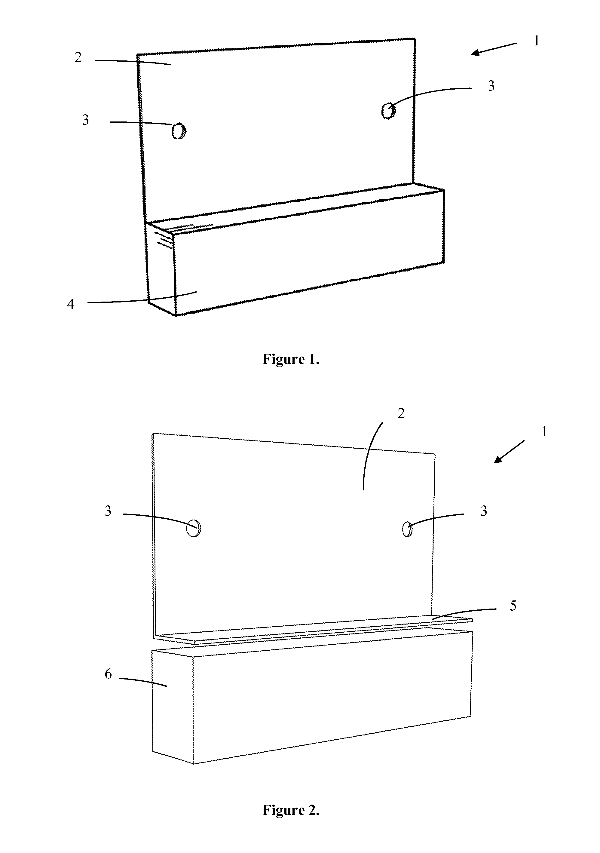
[0043]A jig allows a user to identify and correctly place holes in a wall or other surface for mounting an inventive bracket. Jig 1, seen in FIG. 1, comprises flat plate 2 having an upper edge and lower edge, and a wall face and indicator face. Position holes 3 are disposed in indicator face 2, and correspond to the mounting holes of an inventive bracket. Stop 4 is disposed on the lower edge of flat plate 2 and on the wall face of the jig. Stop 4 allows a user to place the jig against the top of a window opening and the upper edge extending upward toward the ceiling. By orienting jig 1 in this manner, the indicator face of the jig provides the correct location for drilling mounting holes for an inventive bracket. A drill can now be used in position holes 3, or the wall or surface marked for forming mounting holes. The jig is also designed such that placing the jig above the window trim allows a user to drill the position holes so that the bracket can be installed above the window tr...

example 2

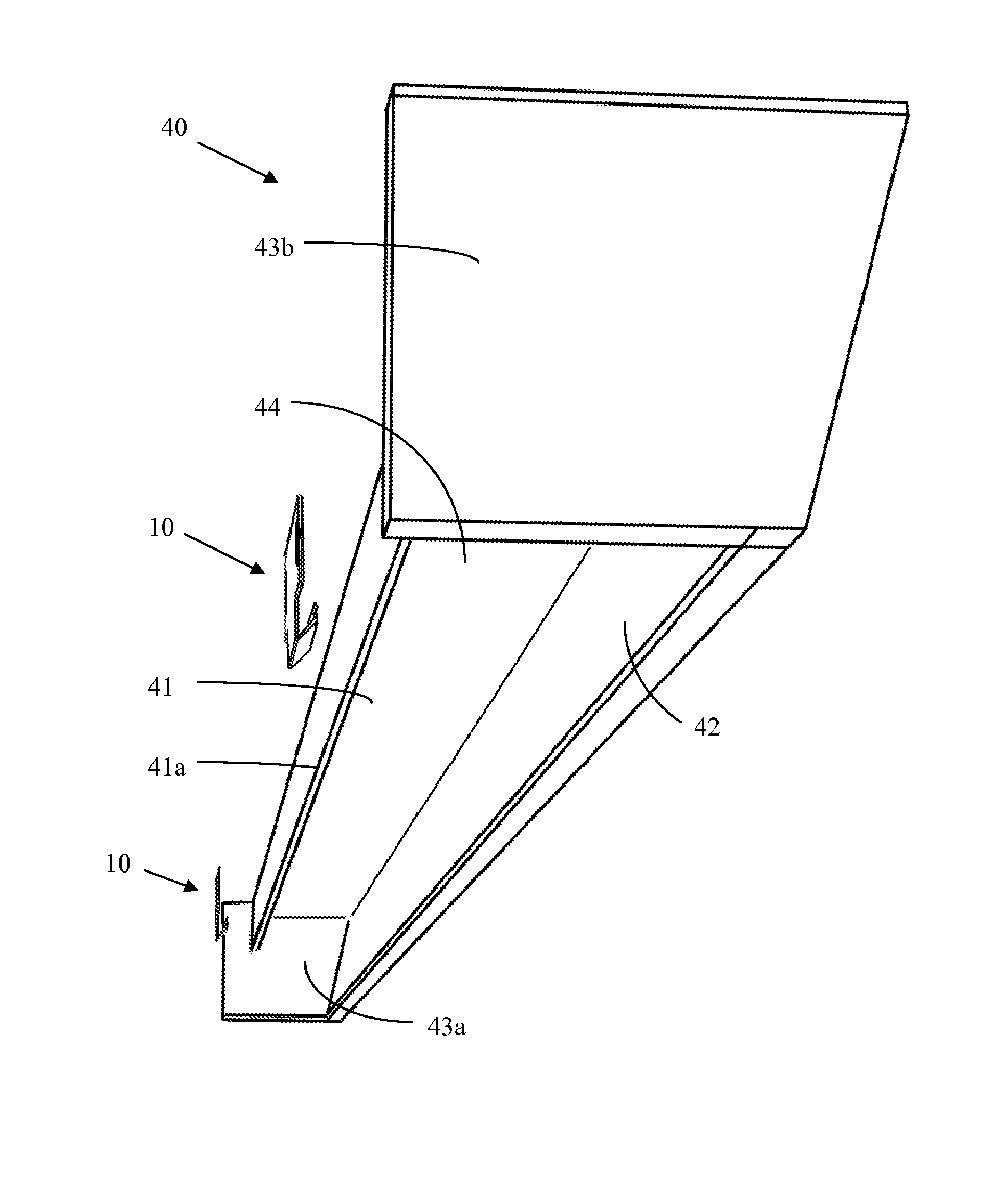
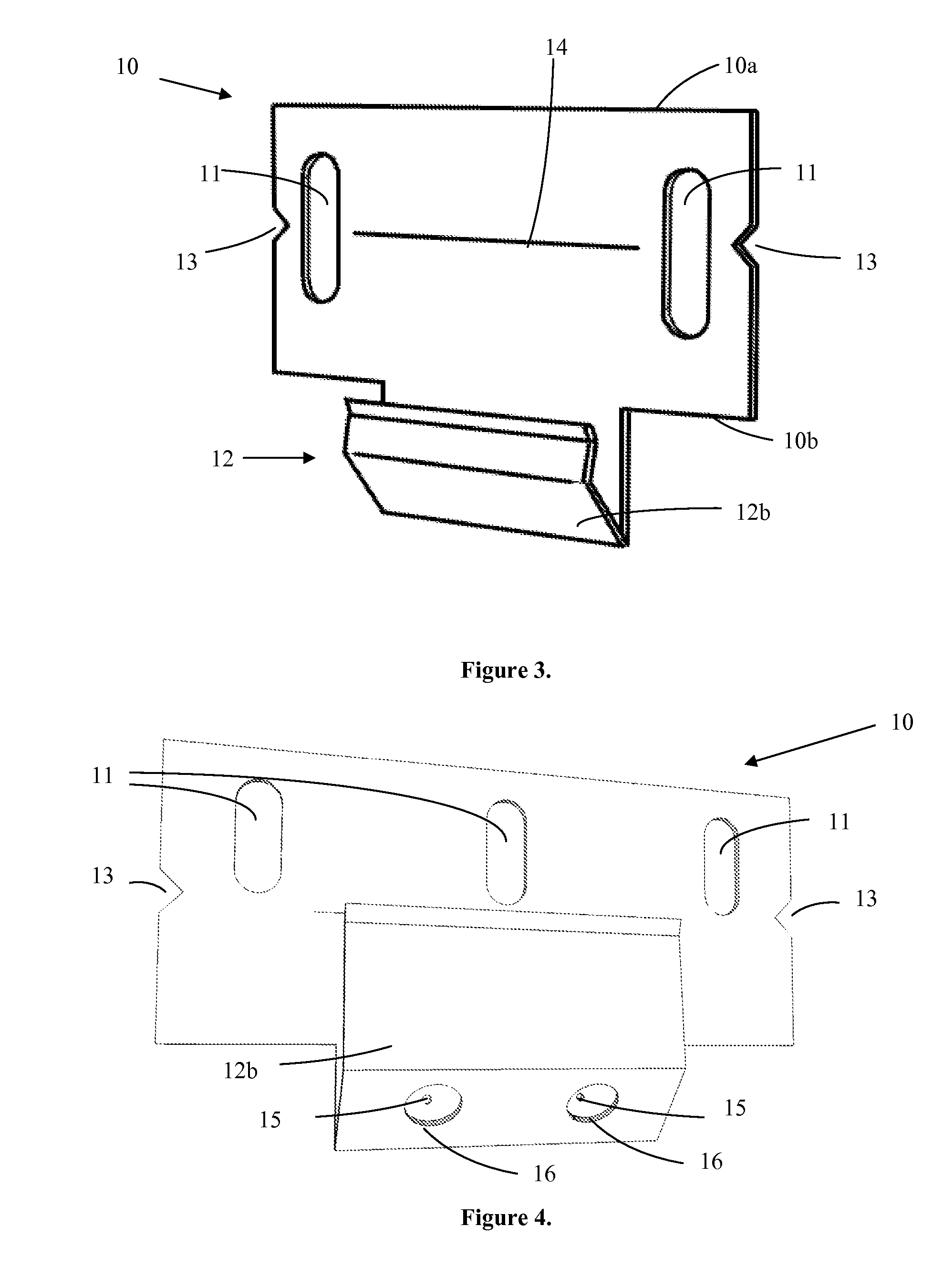
[0045]Bracket 10 has a vertical face having upper edge 10a and lower edge 10b. Mounting holes 11 are disposed on its face. Mounting holes 11 of bracket 10 are specifically designed to be attached to the predrilled holes created by jig 1. As seen in FIG. 3, the holes may be oval, to permit vertical adjustments. However, mounting holes 11 may be circular, or any configuration known in the art. The lower edge of bracket 10 includes clip 12, which extends out from the face of the bracket and is used to hang the cornice.

[0046]The clip has a bend providing backward pressure on the cornice spine pulling it toward the wall. In one embodiment, a beveled clip edge extends from wall face edge 12b of the clip is positioned at a 45 degree angle from the face of bracket 10. The beveled side is opposite to a bevel edge on the spine of the cornice, placing the cornice's weight on the bracket and causing the cornice return to be further drawn against the wall.

[0047]In some variations, the brackets a...

example 3

[0049]Bracket 10 includes a vertical face having upper edge 10a and lower edge 10b. Three oval mounting holes 11 are cut into the vertical face, permitting vertical adjustment of the bracket, as seen in FIGS. 4 and 5. The inclusion of a third, middle hole permits mounting of the bracket to a surface where there is a structural member behind the surface such as a wall stud. In this case only the middle hole would be used, the bracket may self-level. Clip 12 is disposed on lower edge 10b of bracket 10 and extends out from the face of the bracket. Clip 12 has a bend adapted to interface with the cornice spine, as discussed in Example 2.

[0050]As in the above Example 2, bracket 10 may include V-cutout 13 on each side of bracket 10 with level line 14 centered between the cuts to provide a reference for leveling the bracket, as seen in FIGS. 4-6.

[0051]Clip 12 possesses wall face 12a, which is connected to lower edge 10b, and may be an extension of lower edge 10b, and spine-interface 12b. A...


PUM


Abstract

A bracket designed to reduce mounting system failures was designed, having a mounting surface and an angled clip on the lower edge of the mounting surface providing backward pressure for any hardware mounted onto the bracket. The sides of the mounting surface may include cut-outs for aligning multiple brackets. An optional screw-mounting system comprising corresponding holes in the clip, or a tab-mounting system, provide for connecting accessories to the bracket. A cornice centered around a spine element mounted to the bracket. The cornice has a front face and returns attached to either side of the front face, forming the structure. The spine is designed to fit into a plurality of brackets bent to provide backward pressure on the cornice, pulling it toward a mounting surface. The cornice is mounted by fixing the brackets onto a mounting surface and placing the spine of the cornice onto the brackets.

Description

CROSS REFERENCE TO RELATED APPLICATION[0001]This application claims priority to U.S. Provisional Patent Application No. 61 / 422,398, entitled “Spine Centered Cornice System and Method of Mounting”, filed on Dec. 13, 2010, the contents of which are herein incorporated by referenceFIELD OF INVENTION[0002]This invention relates to cornices. Specifically, the invention discloses the construction and mounting of a cornice designed around a spine structure and a complementary mounting bracketBACKGROUND OF INVENTION[0003]Cornice moldings are horizontal decorative molding that crown furniture elements, such as a door or window. Window cornices are designed to conceal or decorate the area above a window and may also be used to conceal a curtain rod. However, windows vary greatly in width forcing the industry to recognize the majority of cornices require custom manufacture and / or installation. The manufacture and installation of custom cornices is expensive and time consuming. As a result, the...

Claims


Application Information

Patent Timeline
IPC IPC(8): A47H2/00
CPCA47H2/00
Inventor HOBART, ROBERT A.WALKER, WILLIAM T.
Owner CORNICESMITH
Why Eureka
Try Eureka