

Truss mounting brace
a technology for mounting brackets and trusses, which is applied in the direction of girders, building repairs, applications, etc., can solve the problems of high risk of installing temporary spacers, time-consuming mounting and removing these temporary spacers, and inability to reus
Active Publication Date: 2014-04-01
SIMPSON STRONG TIE
View PDF169 Cites 18 Cited by
- Summary
- Abstract
- Description
- Claims
- Application Information
AI Technical Summary
Benefits of technology
The truss mounting brace enhances safety by reducing the need for workers to climb, speeds up the installation process, and lowers costs by minimizing crane usage and allowing for precise spacing adherence, thus improving worker safety and reducing installation time and expenses.
Problems solved by technology
Mounting and removing these temporary spacers is time-consuming and they are usually damaged in the process so that they cannot be reused.
Furthermore, installing these temporary spacers is highly dangerous.
At the time of the installation of the trusses no scaffold is present apart from low scaffolds along the front / facade, thus forcing the workers to climb the trusses to attach the spacers.
A drop from such height will cause major injuries for a worker.
During installation of the trusses they are held by a crane which obviously has sufficient strength but often the stability and accuracy is low due to weather and the height of the crane.
Such mounting process is similar to the process of using a lath and equally dangerous.
Method used
View moreImage
Smart ImageViewing Examples

Examples
first embodiment
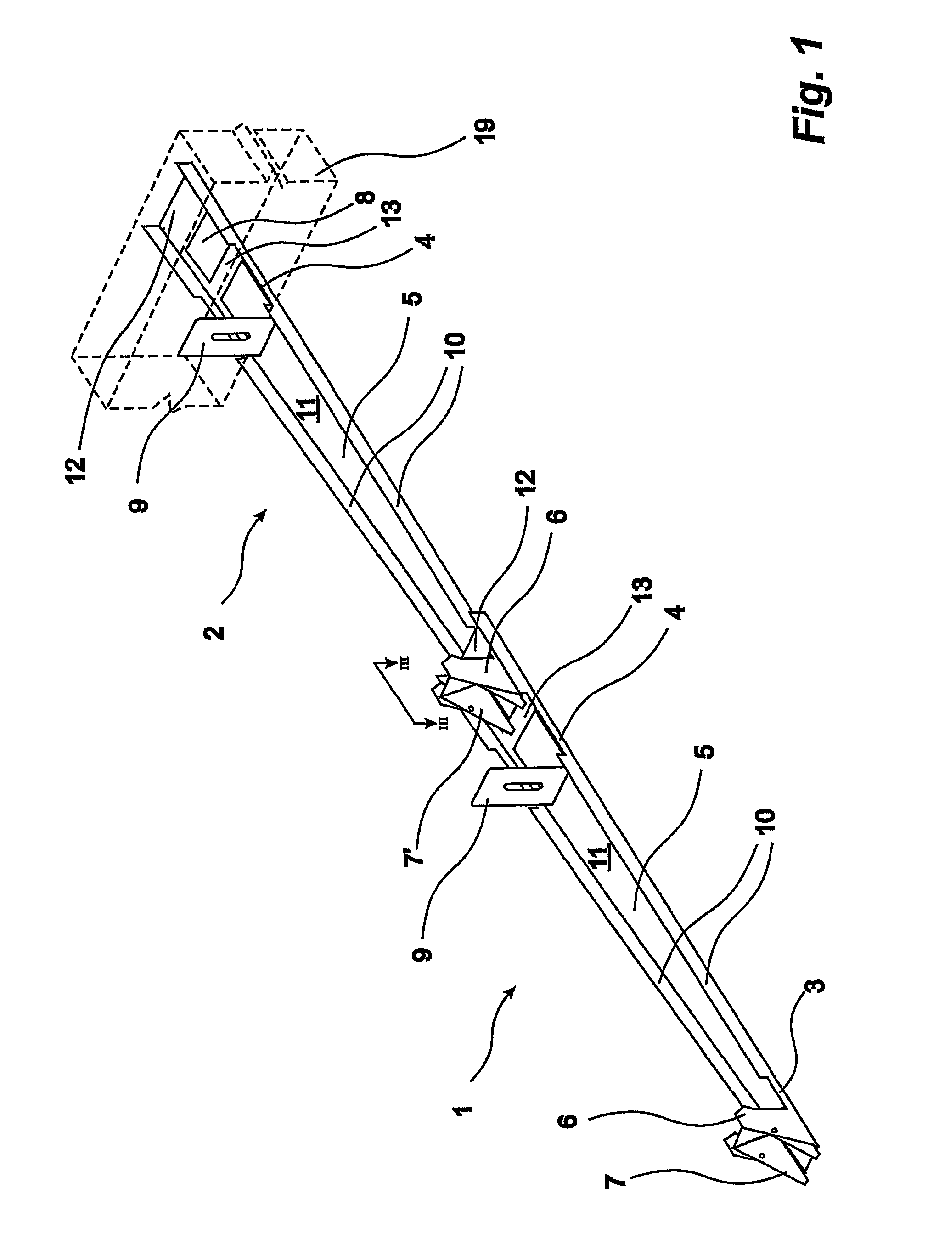
[0035]FIG. 1 shows a perspective view of two engaged truss mounting braces according to the present invention;
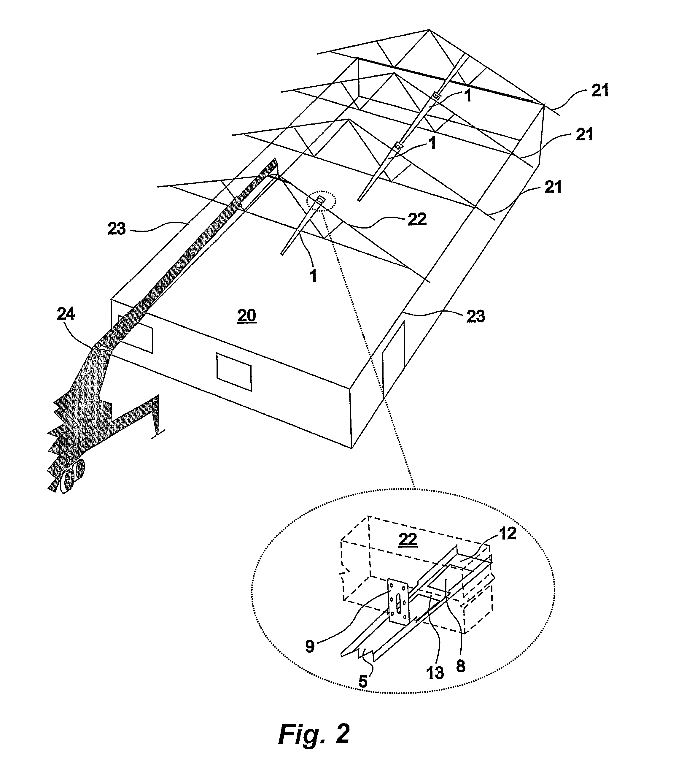
[0036]FIG. 2 shows a perspective view of a structure to which trusses are being mounted using a crane, said trusses coupled by a truss mounting brace according to the present invention;
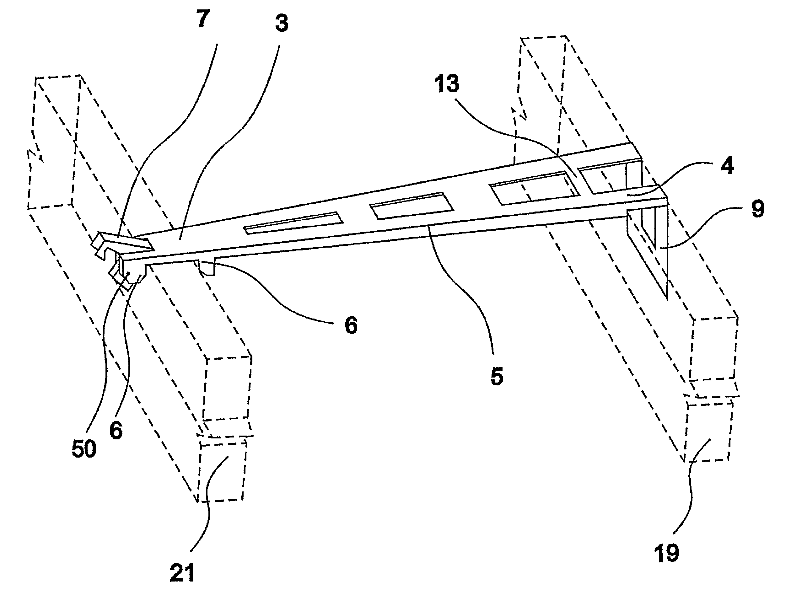
[0037]FIG. 3 shows a sectional view along the line III-III in FIG. 1 showing a gripping section of a truss mounting brace engaged lockingly in a receiving section of a second truss mounting brace;
second embodiment
[0038]FIG. 4 shows a truss mounting brace according to the present invention;
third embodiment
[0039]FIG. 5 shows a truss mounting brace according to the present invention;
Login to View More PUM
| Property | Measurement | Unit |
|---|---|---|
| thickness | aaaaa | aaaaa |
| thickness | aaaaa | aaaaa |
| thickness | aaaaa | aaaaa |
Abstract
A truss mounting brace (1) for use during installation of trusses (19, 21, 22). The truss mounting brace (1) may also be used as a permanent spacer between two trusses (19, 21, 22). The truss mounting brace (1) comprises a mounting section (4) arranged to be mounted on a truss (19, 21, 22), a gripping section (3) and an oblong body section (5) connecting the mounting section (4) and the gripping section (3). The gripping section (3) has a gripping mechanism (6) arranged to receive and to engage another element interlockingly. The present invention also relates to a method of installing two or more trusses, use of the truss mounting brace, and a method of manufacturing the truss mounting brace.
Description
[0001]The present invention relates to a truss mounting brace and, in particular, to a truss mounting brace for use during the installation of trusses. The truss mounting brace of the present invention may also be used as a permanent spacer between two or more trusses.BACKGROUND ART[0002]During the construction of a building, the walls are typically built or installed first whereupon the roof trusses are installed on the top of the walls. These roof trusses support the actual roof, e.g. plates or tiles.[0003]At present, workers typically space and hold the roof trusses during installation by temporarily nailing a batten, a piece of splitwood or similar across adjacent trusses. When the permanent lathing or sheathing is attached to the trusses the temporary batten / spacers need to be removed. Mounting and removing these temporary spacers is time-consuming and they are usually damaged in the process so that they cannot be reused. Furthermore, installing these temporary spacers is highl...
Claims
Login to View More Application Information
Patent Timeline
 Patent Type & AuthorityPatents(United States)
IPC IPC(8): E04C3/02
CPCE04B7/022E04C3/02E04C2003/026E04G21/1891Y10T29/49625
InventorFRIIS, NIELS
OwnerSIMPSON STRONG TIE