Rigid tipped riblets

a technology of rigid ribs and ribs, which is applied in the direction of mechanical equipment, air-flow influencers, transportation and packaging, etc., can solve the problems of reducing the durability of the surface, reducing the service life of the structure, and existing solutions with polymeric tips that may easily deform hundreds of percent with fingernail pressure, etc., and achieves the effect of greater flexibility

Active Publication Date: 2014-04-01
THE BOEING CO
View PDF45 Cites 26 Cited by
  • Summary
  • Abstract
  • Description
  • Claims
  • Application Information

AI Technical Summary

Benefits of technology

[0011]For greater flexibility in certain applications, each tip is longitudinally segmented.

Problems solved by technology

However in service use such as on an aircraft aerodynamic surface, polymers are relatively soft and thus reducing the durability of the surface.
Existing solutions with polymeric tips may readily deform hundreds of percent with fingernail pressure and may be unrecoverable.
Such structures may be undesirable in normal service use on an aircraft or other vehicle.
However, many elastomers and other polymers may not be compatible with Skydrol® or other aircraft fluids or solvents.

Method used


Image

  • Rigid tipped riblets
  • Rigid tipped riblets
  • Rigid tipped riblets

Examples


first embodiment

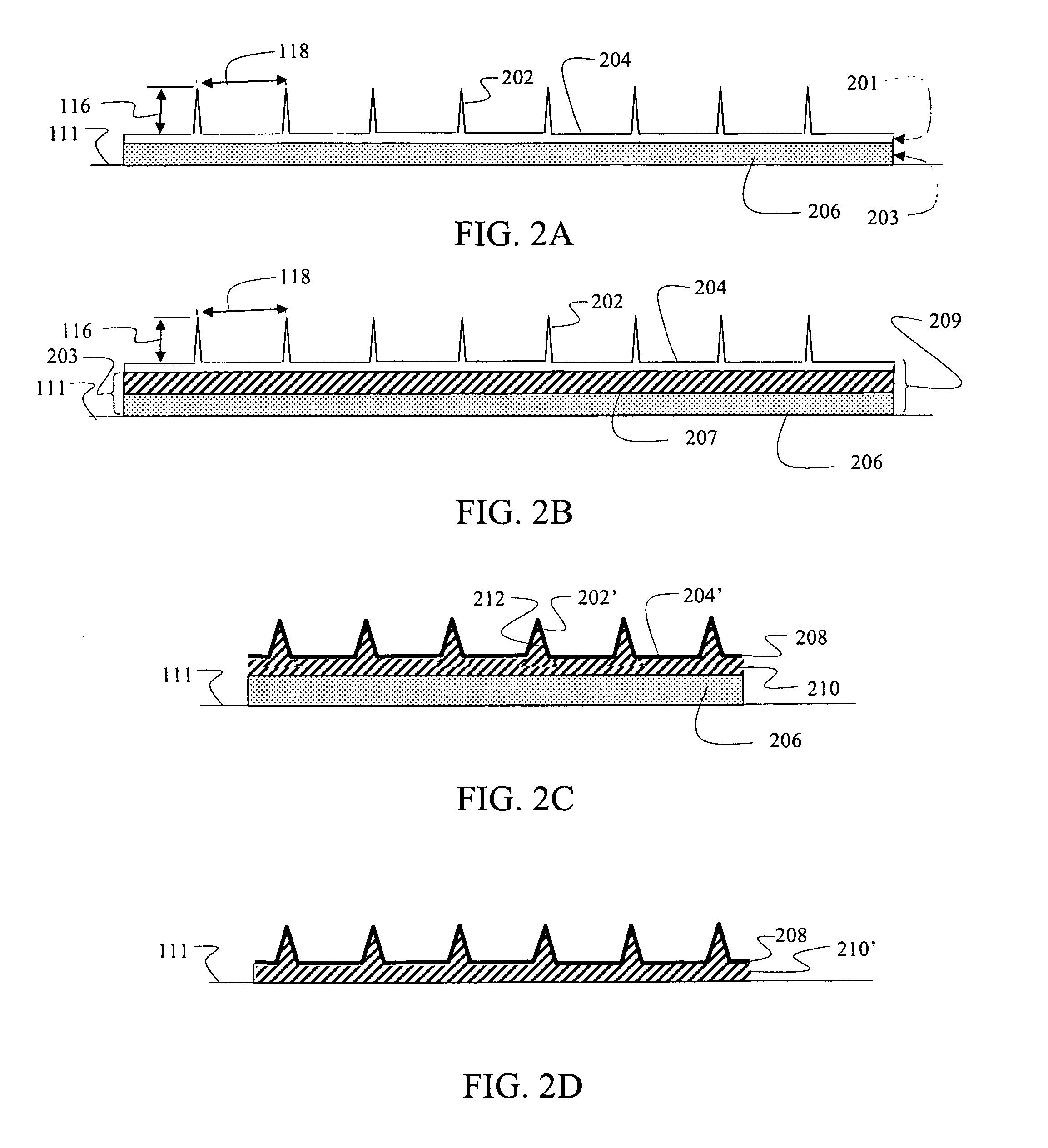
[0039]A first embodiment for rigid tipped riblets is shown in FIG. 2A as a multilayer construction. Individual tips 202 of the riblets protrude from a surface layer 204 to provide a first layer 201 of the multilayer construction. The protruding riblets and continuous surface layer are formed by casting or deposition, as will be described in greater detail subsequently, of the rigid material desired for providing a first characteristic of durability. In an exemplary embodiment, nickel is employed. For the embodiment shown in FIG. 2A a second layer 203 created by an adhesive layer 206 is deposited on a bottom 204a of the surface layer 204. Exemplary adhesives for use in various embodiment may include, without limitation, acrylic pressure sensitive adhesive, sylilated polyurethane pressure sensitive adhesive; thermoplastic adhesive; heat-reactive adhesive or epoxy adhesive. In alternative embodiments, a supporting polymer layer 207 engages the surface layer 204 intermediate the surface...

third embodiment

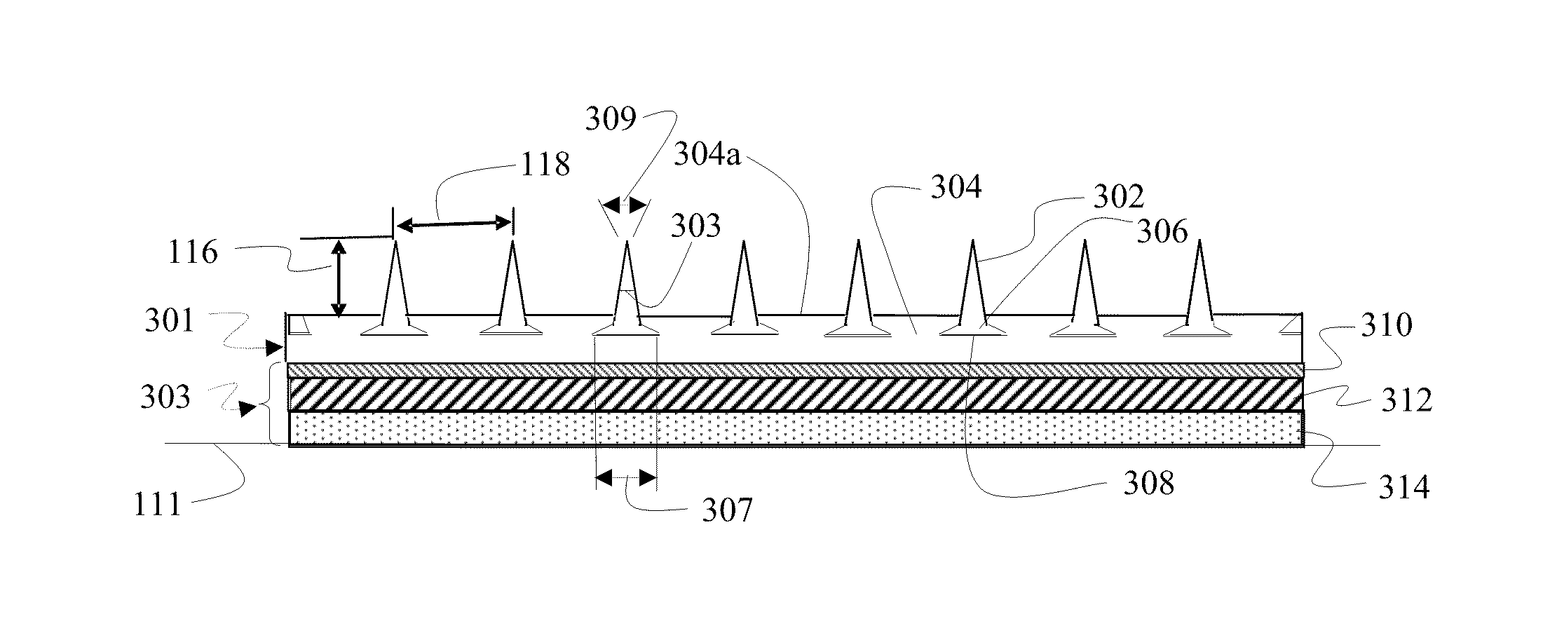
[0046]FIG. 4 demonstrates a third embodiment for the rigid tipped riblets 112 in FIG. 1 which takes advantage of the structural capability provided by the material from which the riblets 112 are formed to allow a sharper profile of tips 402. For the embodiment shown in each of the tips 402 extends from a base 406 supported in an elastomer layer 404. As with the embodiment described with respect to FIG. 3 the base 406 of each tip 402 is surrounded by the elastomer to structurally retain the base 406 within the elastomer layer 404. In alternative embodiments, the extended bottom surface 408 of the base 406 may be adhered to the surface 404a of the elastomer layer 404. The embodiment of FIG. 4 also employs riblet tips 402 separated perpendicular to the flow direction 114 as in the embodiment of FIG. 3. However, in alternative embodiments a continuous surface layer 204 from which the tips 202 extend as disclosed for the embodiment described with respect to FIG. 2A may be employed.

[0047]...


PUM

PropertyMeasurementUnit
internal angleaaaaaaaaaa
durabilityaaaaaaaaaa
metallicaaaaaaaaaa

Abstract

A multilayer construction for aerodynamic riblets includes a first layer composed of a material with protuberances, the first layer material exhibiting a first characteristic having long-term durability and a second layer composed of a material, exhibiting a second characteristic with capability for adherence to a surface.

Description

REFERENCE TO RELATED APPLICATIONS[0001]This application is copending with U.S. patent application Ser. No. 12 / 361,882 filed on Jan. 29, 2009 entitled Shaped Memory Riblets and U.S. patent application Ser. No. 12 / 361,918 filed on Jan. 29, 2009 entitled Amorphous Metal Riblets the disclosures of which are incorporated herein by reference.BACKGROUND INFORMATION[0002]1. Field[0003]Embodiments of the disclosure relate generally to the field of surface geometries for aerodynamic improvements to aircraft or surfaces having a flow interface and more particularly to embodiments and fabrication methods for rigid riblets having improved damage resistance.[0004]2. Background[0005]Increasing fuel efficiency in modern aircraft is being accomplished through improvement in aerodynamic performance and reduction of structural weight. Recent advances in the use of microstructures such as riblets on aerodynamic surfaces have shown significant promise in reducing drag to assist in reducing fuel usage. R...

Claims


Application Information

Patent Timeline
Patent Type & Authority Patents(United States)
IPC IPC(8): B64C21/10B64C1/38
CPCF15D1/004B32B3/30Y02T50/166B32B25/08B64C21/10B64C2230/26B32B15/08B32B27/283B32B27/288B32B27/34B32B27/38B32B27/40B32B2250/02B32B2307/416B32B2307/50B32B2307/702B32B2605/18B64C1/38F15D1/0035Y10T428/24612Y02T50/10F15D1/0085
Inventor RAWLINGS, DIANE C.MALONE, KEVIN R.
Owner THE BOEING CO
Why Eureka
Try Eureka