Monitoring a suspension and traction means of an elevator system

a technology of suspension and traction means and elevator system, which is applied in the direction of elevators, resistance/reaction/impedence, instruments, etc., can solve problems such as falsification of overall safety, and achieve the effect of avoiding excessively expensive replacement and high level of safety of the elevator system

Active Publication Date: 2014-04-01
INVENTIO AG
View PDF10 Cites 43 Cited by
  • Summary
  • Abstract
  • Description
  • Claims
  • Application Information

AI Technical Summary

Benefits of technology

[0009]An objective is therefore now to eliminate the said disadvantages of conventional monitoring devices, and to propose a monitoring device for suspension-and-traction means that delivers more accurate and qualitatively classifiable information about its state, thereby achieving a higher level of safety for the elevator system, and avoiding cost-intensive excessively early replacements of the suspension-and-traction sheaves.
[0021]In principle, with a monitoring device that is embodied in this manner, it is possible to determine the “quality” of an impending cord-break, since the specific resistance of a single cord increases when its cross-sectional area decreases due to increasing breakage of the individual strands. It is, however, preferable to select the mutually differing resistors at the ends of the cords with a magnitude that is a factor greater than the specific resistance of the cord, this factor lying in a range from 500 to 1500, but preferably having a value of approximately 1000. In this manner, a reliable independence of the measurement signal from the mutually differing resistances of the specific resistance of the cord is assured, which varies not only as a function of the cross-sectional area, but also in response to temperature differences which, in a tall elevator hoistway, can be considerable.
[0028]Also in a monitoring device that is intended for suspension-and-traction means with a plurality of cords, the resistance elements, and / or the resistors, are preferably arranged mirror-inverted. In other words, in the case of three cords, the mutually differing resistors at the one adjacent ends of the cords have the characteristics x, y, z, while the resistors at the other adjacent ends of the cords have the characteristics z, y, x. The sum of the two resistors that are arranged in this manner on a single cord remains constant. Also, the sum of the resistors that are arranged in parallel at the one ends, preferably in one single first contacting element for all of the cords, and / or the sum of their characteristics x+y+z, is hence identical to the sum of the resistors that are arranged in parallel at the other ends, also preferably in one single second contacting element for all of the cords, and / or to the sum of their characteristics z+y+x. This does not impair the usability of the measurement results that are obtained, and brings the advantage of less expensive series manufacture.
[0030]The disclosed monitoring devices are preferably combinable with a reverse-bending counter, so that a further information flows into the—preferably processor-aided—monitoring device, and hence the detection of the need for replacement of a suspension-and-traction means becomes even more reliable.
[0032]In summary, such a monitoring device brings the following advantages:

Problems solved by technology

However, disadvantageous in all of these known monitorings of the suspension-and-traction means is that the information about the signs of wear, or about the prevailing anomalous state of the suspension-and-traction means, is present only as an overall result.
In particular, cross-connections (short circuits) between cords greatly falsify the overall result.

Method used


Image

  • Monitoring a suspension and traction means of an elevator system
  • Monitoring a suspension and traction means of an elevator system
  • Monitoring a suspension and traction means of an elevator system

Examples


Embodiment Construction

[0045]The following detailed description and appended drawings describe and illustrate various exemplary embodiments of the invention. The description and drawings serve to enable one skilled in the art to make and use the invention, and are not intended to limit the scope of the invention in any manner. In respect of the methods disclosed, the steps presented are exemplary in nature, and thus, the order of the steps is not necessary or critical.

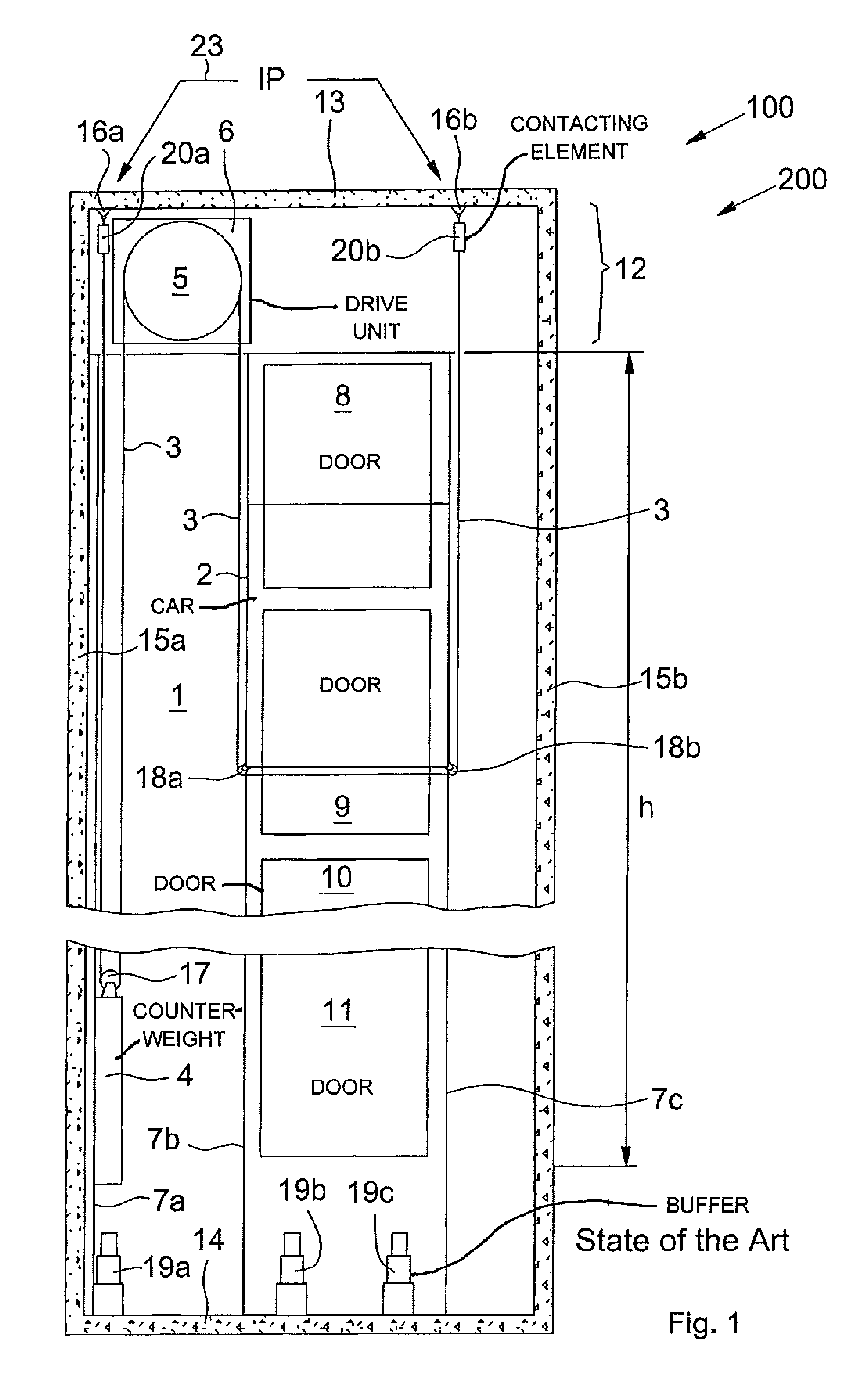
[0046]FIG. 1 shows an elevator system 100 as known from the state of the art, for example in the 2:1 roping arrangement that is shown. Arranged movably in an elevator hoistway 1 is an elevator car 2, which is connected via a suspension-and-traction means 3 to a movable counterweight 4. In operation, the suspension-and-traction means 3 is driven by a traction sheave 5 of a drive unit 6, which is arranged in a machine room 12 in the top area of the elevator hoistway 1. The elevator car 2 and the counterweight 4 are guided by means of guiderail...


PUM


Abstract

A monitoring device for a suspension-and-traction apparatus of an elevator system that includes at least one electrically conductive cord contains a measurement apparatus for determining a resulting resistance. The measurement apparatus is connected to the cord with contacting elements contacting opposite ends of cord. Damage to the suspension-and-traction apparatus is detected by a contact point that can register protruding conductive parts of the cord and, in another embodiment, the contacting elements each contain a plurality of mutually differing resistance elements such that each of at least two electrically conductive cords of the suspension-and-traction apparatus is connected to the monitoring device through two of the resistance elements.

Description

FIELD OF THE INVENTION[0001]The present invention relates to an elevator system, in which at least one elevator car, or at least one lift cage, and at least one counterweight are moved in opposite directions in an elevator hoistway, wherein the at least one elevator car and the at least one counterweight run along guiderails, are supported by one or more suspension-and-traction means, and are driven by a traction sheave of a drive unit. The present invention relates particularly to the one or more suspension-and-traction means, viz. to a method of monitoring the one or more suspension-and-traction means of the elevator system, and to a device according to the invention for executing this method.BACKGROUND OF THE INVENTION[0002]In elevator systems it has proved advantageous to use suspension-and-traction means that are composed of at least one electrically conductive steel rope and non-conductive sheath, or of ropes made of special plastics, in which an electric conductor is integrat...

Claims


Application Information

Patent Timeline
Patent Type & Authority Patents(United States)
IPC IPC(8): G01R27/08B66B1/34
CPCB66B7/1223
Inventor BERNER, OLIVERANNEN, MICRO
Owner INVENTIO AG
Why Eureka
Try Eureka