Emitter driver for noninvasive patient monitor

a non-invasive, patient technology, applied in the field of patient monitoring devices, can solve the problems increasing patient comfort, etc., and achieve the effects of increasing cable stiffness, increasing cable size, and increasing patient comfor

Active Publication Date: 2014-04-01
MASIMO CORP
View PDF422 Cites 249 Cited by
  • Summary
  • Abstract
  • Description
  • Claims
  • Application Information

AI Technical Summary

Benefits of technology

[0014]The foregoing LED driver circuits 108, 208 include some limitations. The driver circuit 108 uses a separate drive conductor for each LED of the light source 110. Thus, in the system 100 of FIG. 1, the cable 106 carries N drive currents over N conductors to drive N LEDs. As will be recognizable to an artisan from the disclosure herein, increasing a number LEDs in the light source 110 to, for example, increase a number of available wavelengths, corresponds to increasing a number of conductors in the cable 106. Each increase of conductors carrying high emitter driver currents in the cable increases a likelihood of interference with other conductors of cable 106, such as those conductors communicating sensitive very low currents or voltages at high impedance as output signals from the detectors of the sensor 104. Moreover, each increase of conductors increases cable size, cost, complexity, shielding, cable stiffness, and the like, thereby decreasing patient comfort.
[0015]Driver circuit 208, including the row and column drivers 220, 222, is an improvement to the N-to-N driver circuit 108 of FIG. 1. For example, in the system 200 of FIG. 2, the cable 206 carries N high emitter driver currents on N conductors. Half of the N conductors correspond to high current row drive signals and half correspond to high current column drive signals. These N conductors allow a processor to address and thus activate specific nodes of a light source grid array of 2*N nodes. Similar to the N-to-N driver circuit 108, an artisan will recognize from the disclosure herein, that increasing a number LEDs in the light source grid array 210 to, for example, increase a number of available wavelengths, corresponds to increasing a number of conductors in the cable 206, thereby potentially increasing a likelihood of harmful interference in detector signals.

Problems solved by technology

Moreover, each increase of conductors increases cable size, cost, complexity, shielding, cable stiffness, and the like, thereby decreasing patient comfort.
However, simply increasing a number of high current conductors in a given cable 106, 206 can be fraught with drawbacks including cable stiffness and crosstalk noise on detector conductors.

Method used


Image

  • Emitter driver for noninvasive patient monitor
  • Emitter driver for noninvasive patient monitor
  • Emitter driver for noninvasive patient monitor

Examples


Embodiment Construction

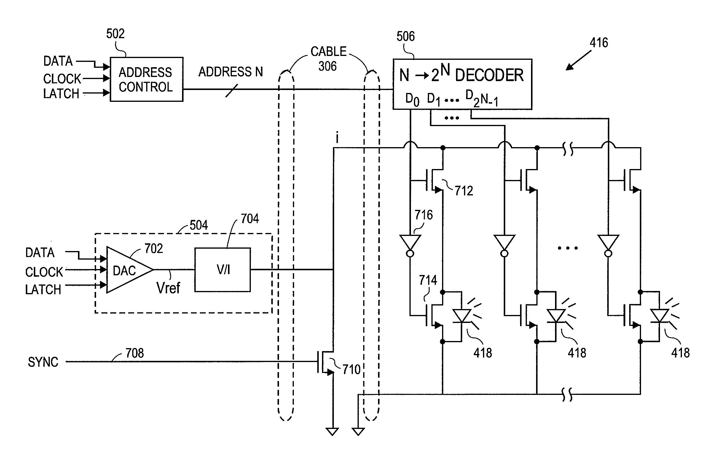
[0032]Embodiments of the present disclosure include a patient monitoring system including a patient monitor having a driving circuit advantageously capable of selectively activating 2N LEDs of a light source using a decoder receiving an N signal address. In various disclosed embodiments, use of addressing and a decoder advantageously reduces a number of high current conductors in a cable communicating signals between the monitor and, for example, a noninvasive sensor. For example, in embodiments where a light source includes LEDs configured to be driven by a single current, embodiments of the present disclosure provide that the cable may carry a single high current conductor. In other embodiments where the light source includes LEDs configured to be driven at a first current and additional LEDs configured to be driven at a second current different from the first, embodiments of the present disclosure provide that the cable may carry the plurality of high current conductors, one for ...


PUM


Abstract

Embodiments of the present disclosure include an emitter driver configured to be capable of addressing substantially 2N nodes with N cable conductors configured to carry activation instructions from a processor. In an embodiment, an address controller outputs an activation instruction to a latch decoder configured to supply switch controls to activate particular LEDs of a light source.

Description

REFERENCE TO RELATED APPLICATIONS[0001]The present application claims priority benefit under 35 U.S.C. §119 (e) from U.S. Provisional Application No. 61 / 239,741, filed Sep. 3, 2009, entitled “Emitter Driver for Noninvasive Patient Monitor,” which is incorporated herein by reference.[0002]The present disclosure is related to the following co-pending applications.[0003]applicationFilingSer. No.DateTitle12 / 534,827Aug. 3, 2009Multi-Stream Data Collection System forNoninvasive Measurement of BloodConstituents12 / 534,812Aug. 3, 2009Multi-Stream Sensor Front Ends forNoninvasive Measurement of BloodConstituents12 / 534,823Aug. 3, 2009Multi-Stream Sensor for NoninvasiveMeasurement of Blood Constituents12 / 534,825Aug. 3, 2009Multi-Stream Emitter for NoninvasiveMeasurement of Blood Constituents12 / 497,528Jul. 2, 2009Noise Shielding for a Noninvasive Device12 / 497,523Jul. 2, 2009Contoured Protrusion for ImprovingSpectroscopic Measurement of BloodConstituents29 / 323,409Aug. 25, 2008Patient Monitoring S...

Claims


Application Information

Patent Timeline
Patent Type & Authority Patents(United States)
IPC IPC(8): A61B5/00
CPCA61B5/0059A61B2562/0233A61B2562/046A61B5/6826A61B2560/045A61B2562/222A61B5/14552
Inventor BRUINSMA, JOHANNESDALVI, CRISTIANOLAMEGO, MARCELO
Owner MASIMO CORP
Why Eureka
Try Eureka