Geared motor for an active roll stabilizer

Active Publication Date: 2014-04-08
SCHAEFFLER TECH AG & CO KG
View PDF29 Cites 12 Cited by
  • Summary
  • Abstract
  • Description
  • Claims
  • Application Information

AI Technical Summary

Benefits of technology

[0005]The object of the present invention is to specify a slewing motor in which a faulty behavior of the active roll stabilizer is significantly reduced.
[0006]According to the invention, a torsion element, whose rotational rigidity is lower than the rotation rigidity of the stabilizer, is effectively arranged between the drive and the one stabilizer half ensures that small relative rotations between the two stabilizer halves are permitted without appreciable movements occurring in the slewing motor between drive and housing or stator. According to the invention, the rigid connection, provided in the prior art, between the stabilizer half and the drive of the slewing motor is interrupted by the torsion element according to the invention. According to the invention, a rigidity step is provided between the two stabilizer halves, with the result that, between the two stabilizer halves with comparatively high rigidity values, an element with a relatively low rotational rigidity value permits rotations between the two stabilizer halves without appreciable rotation at the intermediately connected slewing motor.
[0007]On the stator side, the slewing motor can be connected to the one stabilizer half. On the stator side, a housing may be provided in which the rotor is rotatably mounted. This housing

Problems solved by technology

In particular in the case of straight-ahead travel and one-sided springing movement, for example when traveling on uneven roadways, faulty behavior of such active roll stabilizers can have dis

Method used


Image

  • Geared motor for an active roll stabilizer
  • Geared motor for an active roll stabilizer
  • Geared motor for an active roll stabilizer

Examples


Embodiment Construction

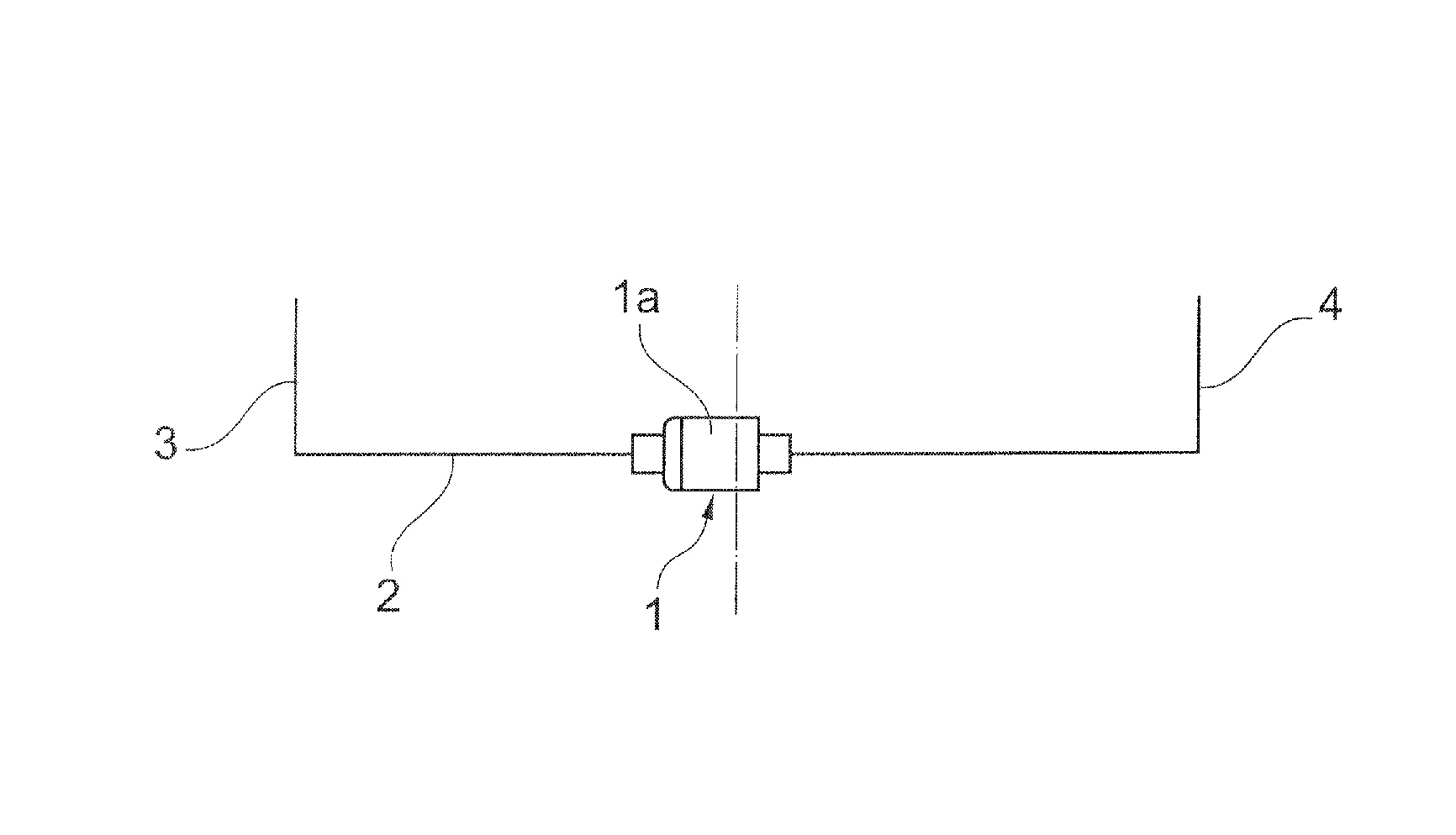
[0027]FIG. 1 is a schematic illustration of an active rolling stabilizer having a slewing motor 1 according to the invention. The slewing motor 1 is connected to a divided stabilizer 2. The stabilizer 2 has two stabilizer halves 3, 4, wherein the one stabilizer half 3 is connected in a rotationally fixed fashion to a motor housing 1a on the stator side. The other stabilizer half 4 is introduced by its free end into the slewing motor 1 and connected to the drive (not illustrated here).

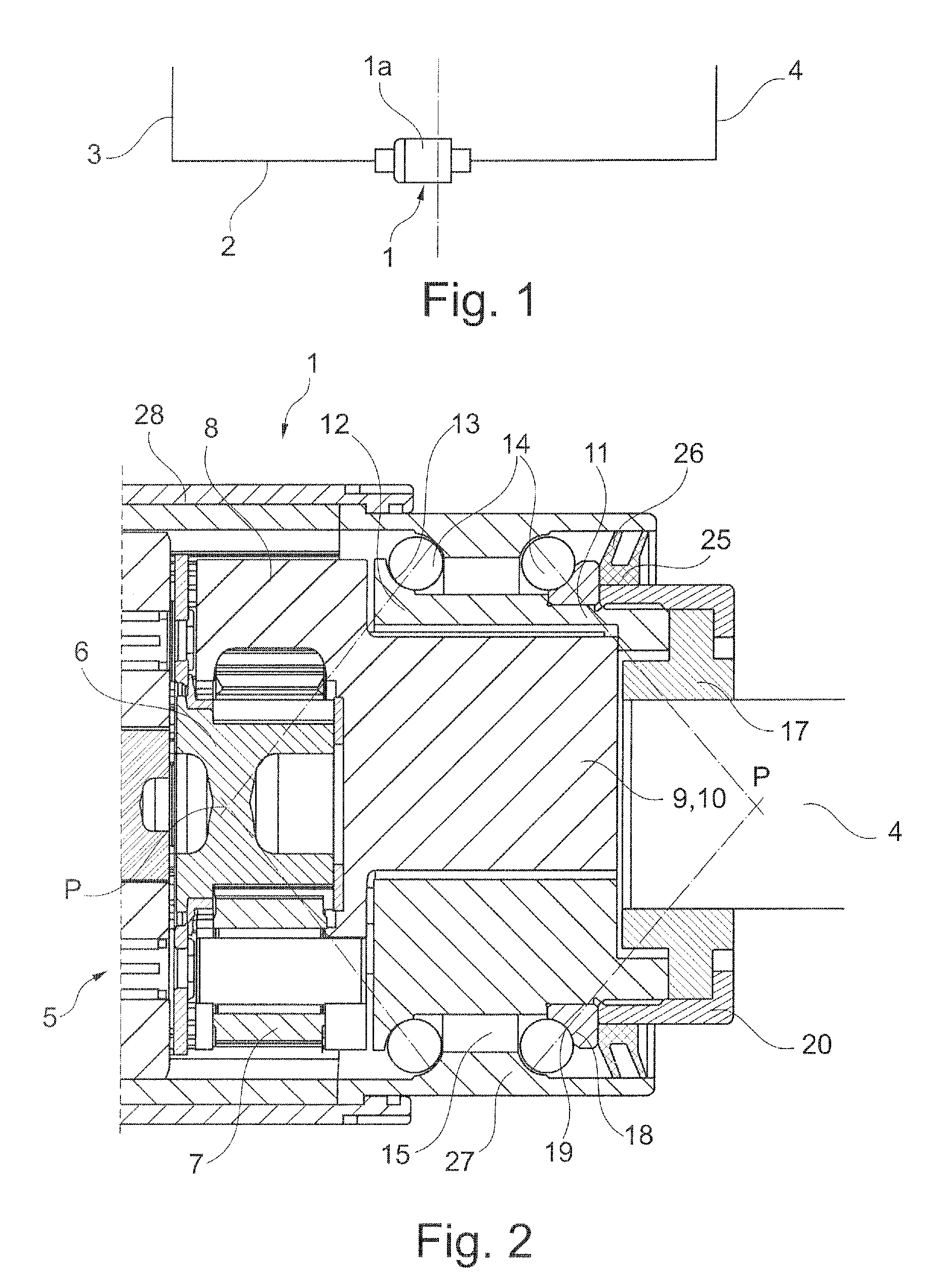
[0028]FIG. 2 shows a longitudinal section of the slewing motor from FIG. 1, with a portion of a planetary gear mechanism 5 being illustrated on the drive of the slewing motor 1 here. A sun gear 6 meshes with planetary gears 7 which are rotatably mounted on a planetary carrier 8. A drive part 9 is integrally formed on the planetary carrier 8.

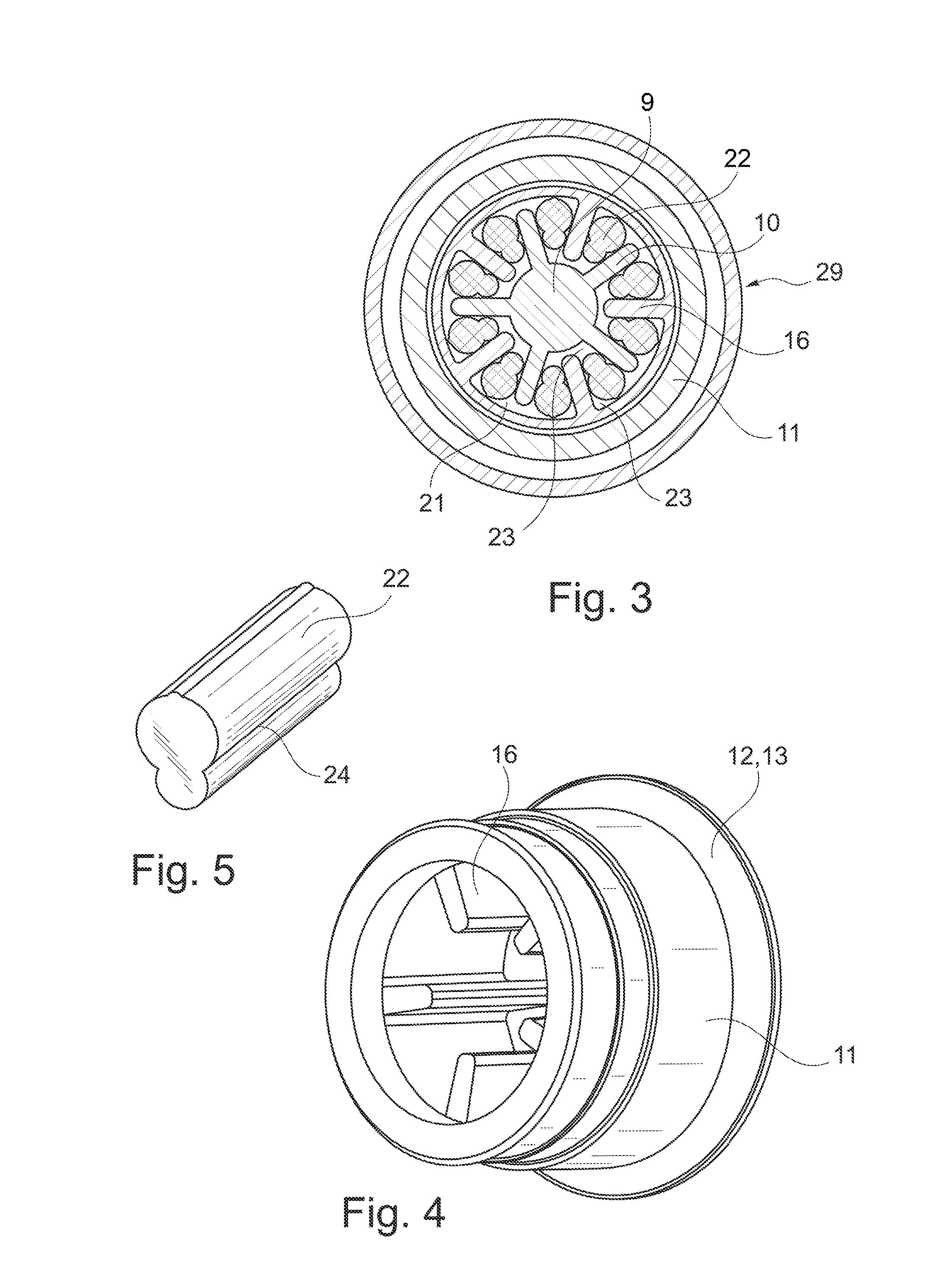
[0029]The planetary carrier 8 with the integrally formed-on drive part 9 is clearly illustrated in a perspective view in FIG. 6. It is apparent here that the drive p...


PUM


Abstract

A slewing motor for an active roll stabilizer, which can be connected by its drive to one stabilizer half, and which can be connected on the stator side to another stabilizer half of a divided stabilizer. A torsion element, whose rotational rigidity is lower than the rotational rigidity of the stabilizer, is effectively arranged between the drive and the one stabilizer half.

Description

[0001]This application claims the priority of DE 10 2009 006 385.4 filed Jan. 28, 2009, which is incorporated by reference herein.BACKGROUND OF THE INVENTION[0002]The present invention relates to a slewing motor for an active roll stabilizer such as is used in modern motor vehicles for avoiding rolling movements of the vehicle body. The slewing motor is used here selectively to build up and reduce forces which counteract the rolling.[0003]DE 10 2005 031 414 A1 has disclosed, for example, a slewing motor for compensating for vehicle movements, wherein this slewing motor is arranged in a stabilizer and is connected to the two ends (facing one another) of a first stabilizer half and of a second stabilizer half.[0004]In particular in the case of straight-ahead travel and one-sided springing movement, for example when traveling on uneven roadways, faulty behavior of such active roll stabilizers can have disadvantageous effects. The cause of this faulty behavior is the relative rotation b...

Claims


Application Information

Patent Timeline
IPC IPC(8): F16D3/10B60G21/055
CPCB60G2202/22B60G2204/4191B60G21/0555F16D3/68F16F15/1245
Inventor GRAU, ULRICHMAYER, RALF
Owner SCHAEFFLER TECH AG & CO KG
Why Eureka
Try Eureka