
Method for controling air flow rate of air conditioning system

Inactive Publication Date: 2005-07-21
LG ELECTRONICS INC
View PDF12 Cites 11 Cited by
  • Summary
  • Abstract
  • Description
  • Claims
  • Application Information

AI Technical Summary

Benefits of technology

[0012] An object of the present invention is to provide a method for controlling an air flow rate of an air conditioning system, which can deal with a level of room air pollution, and sharp change of the pollution level, appropriately.
[0016] Preferably, the flow rate of the air for cleaning or ventilating a room is controlled to be the highest flow rate when the concentration value is high, and the value of concentration change is high or medium, and the high flow rate when the concentration value is high, and the value of concentration change is low, or the concentration value is medium, and the value of concentration change is high.
[0022] The (c3) step may include the step of rotating at least one of the first fan and the second fan at the high speed when the concentration value is high, and the value of the concentration change is low.

Problems solved by technology

However, since the air of a shut tight room is polluted gradually as time goes by, the air conditioning system ventilates the room periodically, to supply fresh air to the room.
However, since the foregoing typical air conditioning system is operative only taking the room temperature into account without a level of air pollution of the room, the air conditioning system fails to reflect very important factors, such as the level of pollution of the room air, and a rate of pollution of the room air, to the operation.
Moreover, in a case the room air is polluted rapidly due to various reasons, such as someone in the room smokes, or many persons use the room suddenly, or the like, typical air conditioning system can not deal with the change of room air, appropriately.

Method used


Image

  • Method for controling air flow rate of air conditioning system
  • Method for controling air flow rate of air conditioning system
  • Method for controling air flow rate of air conditioning system

Examples


Embodiment Construction

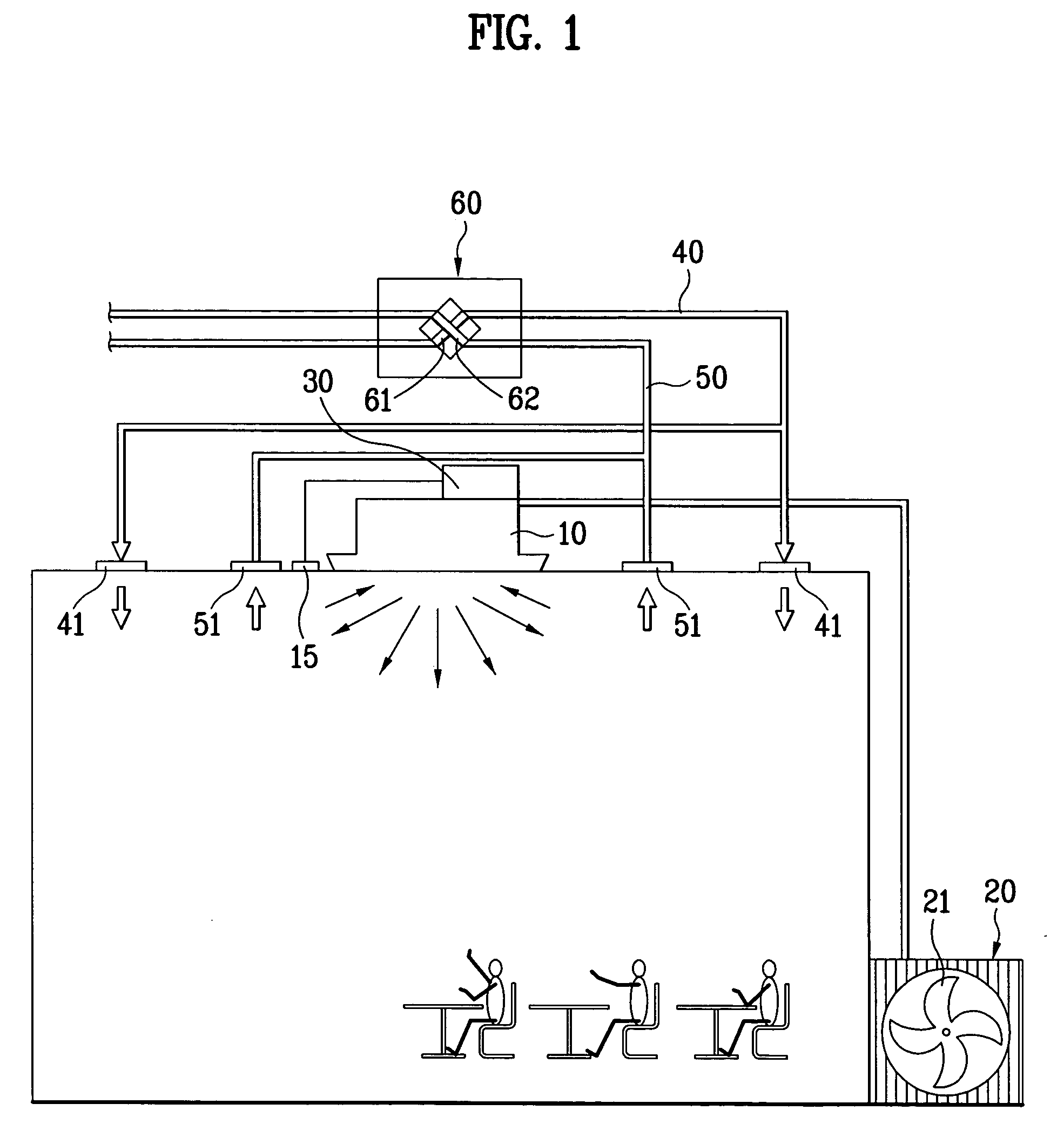
[0034] Reference will now be made in detail to the preferred embodiments of the present invention, examples of which are illustrated in the accompanying drawings. In describing the embodiments, identical parts will be given the same names and reference symbols, and repetitive description of which will be omitted. FIG. 1 illustrates a diagram of an air conditioning system, schematically.

[0035] Referring to FIG. 1, there is an indoor unit 10 installed on a ceiling of a room so as to be in communication with a room. The indoor unit 10 includes an expansion device (not shown) for expanding refrigerant, an indoor heat exchanger (not shown) for making the expanded refrigerant to heat exchange with the room air, and an indoor fan (not shown) for drawing the room air into the indoor unit 10, and supplying the room air to the room again via the indoor heat exchanger.

[0036] Though not shown, the indoor unit 10 has a filter assembly provided therein. The filter assembly 10 removes foreign ma...


PUM


Abstract

Method for controlling an air flow rate of an air conditioning system, including the steps of measuring a concentration of volatile organic compounds in air periodically, calculating a value of concentration change from concentration values measured at the present time and in the past, and controlling the flow rate of air for cleaning or ventilating a room with reference to the present concentration and value of concentration change, whereby controlling a flow rate of room cleaning or ventilating air to cope, not only with concentration of organic compounds, but also with rapid change of the concentration of the organic compounds in the air.

Description

[0001] This application claims the benefit of the Korean Application No. P2004-0004152 filed on Jan. 20, 2004, which is hereby incorporated by reference. BACKGROUND OF THE INVENTION [0002] 1. Field of the Invention [0003] The present invention relates to air conditioning systems, and more particularly, to a method for controlling an air flow rate of an air conditioning system, in which a flow rate of room cleaning or ventilating air is controlled to cope, not only with concentration of organic compounds, but also with rapid change of the concentration of the organic compounds in the air. [0004] 2. Background of the Related Art [0005] The air conditioning system is an apparatus for maintaining room air at a most proper state according to use or purpose of the air, inclusive of air conditioners, air cleaners, ventilating devices. The air conditioner cools or heats the room by using a property of the refrigerant in which the refrigerant discharges or absorbs heat to / from an environment...

Claims


Application Information

Patent Timeline
IPC IPC(8): F24F7/00F24F11/00
CPCF24F11/0017Y02B30/78Y02B30/746F24F11/0079F24F11/30F24F2110/50F24F11/77Y02B30/70F24F7/10F24F11/64F24F11/74F24F2110/65
Inventor KIM, KYUNG HWANCHOI, HO SEONYUM, KWAN HO
Owner LG ELECTRONICS INC
Learn More