A kind of optical network unit automatic testing method

An optical network unit, automated testing technology, applied in transmission monitoring/testing/fault measurement systems, electrical components, selection devices for multiplexing systems, etc. growth and other issues to achieve the effect of reducing test costs, reducing overhead costs, and shortening test cycles

Inactive Publication Date: 2018-07-24
PHICOMM (SHANGHAI) CO LTD
View PDF3 Cites 0 Cited by
  • Summary
  • Abstract
  • Description
  • Claims
  • Application Information

AI Technical Summary

Problems solved by technology

[0005] 1. Device and interoperability testing requirements are becoming increasingly complex
[0006] 2. The labor and skills required to test each version are increasing, but staffing is not increasing
[0007] 3. The development speed of testing tools is far behind the speed of tools used in designing new products
(According to incomplete statistics, 80% of the tests still need to be executed manually

Method used


Image

  • A kind of optical network unit automatic testing method
  • A kind of optical network unit automatic testing method

Examples


Embodiment Construction

[0034] Specific embodiments of the present invention will be further described below in conjunction with the accompanying drawings.

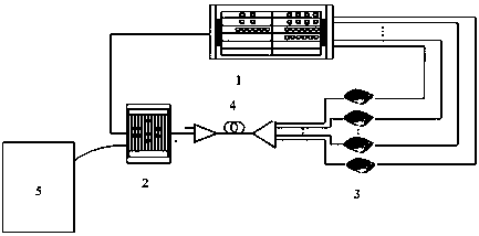
[0035] Such as figure 1 As shown, it is a schematic diagram of an optical network topology applicable to an optical network unit automatic testing method of the present invention, which includes: a data network (Data Networks) 1, an optical line terminal (OLT) 2 connected to the data network 1 and A number of optical network units (ONU) 3 connected in parallel, and an optical splitter 4. One end of the optical splitter 4 is connected to the optical line terminal 2, and the other end is connected to several optical network units 3, wherein the optical line terminal 2 is also connected to the network management server system ( EMS)5.

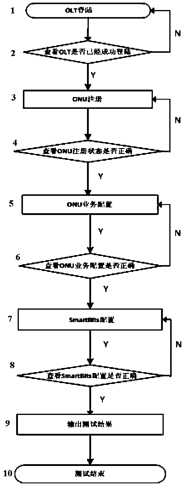
[0036] Such as figure 2 As shown, the optical network unit automated testing method includes the following steps:

[0037] Step 1. Log in the optical line terminal to view relevant information of the optical lin...


PUM


Abstract

The invention discloses an automatic test method for an optical network unit, comprising: 1. Logging in an optical line terminal; 2. Judging whether the optical line terminal is successfully logged in; 3. Registering the optical network unit; 4. Judging whether the registration status of the optical network unit is correct; 5. 1. Business configuration of the optical network unit; 6. Judging whether the business configuration of the optical network unit is correct; 7. Configuring the data network test instrument; 8. Judging whether the configuration of the data network test instrument is correct; 9. Outputting the test result; 10. Ending the test. The present invention can improve test efficiency, shorten test cycle, and reduce test cost in the research and development stage; it can also assist manufacturers to greatly increase their productivity, and the solution enables engineers of different levels to participate in the test automation process, improving the test engineer's productivity. Value, reduced overhead costs, better use of existing resources, and reduced time-to-market.

Description

technical field [0001] The invention relates to a test technology for a passive optical fiber network, in particular to an automatic test method for an optical network unit. Background technique [0002] The passive optical network (PON) system structure is mainly composed of the optical line terminal (OLT, Optical LineTerminal) of the central office, the optical distribution network (ODN, Optical Distribution Network) including passive optical devices, and the optical network unit / optical network terminal of the user end (ONU / ONT Optical Network Unit / Optical Network Terminal). Compared with active optical access technology, PON eliminates the active equipment between the central office and the user end, which makes maintenance simple, high reliability, low cost, and can save fiber resources, making PON technology the future optical fiber The main solution for to-the-home (FTTH). With the gradual reduction of PON cost and the gradual expansion of application scale, the t...

Claims


Application Information

Patent Timeline
Patent Type & Authority Patents(China)
IPC IPC(8): H04B10/07H04Q11/00
Inventor 苏赵珍
Owner PHICOMM (SHANGHAI) CO LTD
Why Eureka
Try Eureka